by Mai Vang, Marketing Director | Jul 19, 2023
This 1-day course is designed for engineers who are analyzing the curing process of layered composites. The training will cover the correct and efficient use of this technology for the purpose of simulating the composite curing process to determine degree of cure and process-induced distortions and stresses. Attendees will also learn how to compensate for these distortions in the tool surface so that the final composite structure meets the desired specifications.
Prerequisites for this course are DRD’s Introduction to Ansys Mechanical course and DRD’s Ansys Composite PrepPost course or equivalent practical experience using Ansys Mechanical and ACP. This is a challenging course for proficient users. Please do not register for this course if you do not have the prerequisites. Please contact DRD if you have questions or would like to discuss this with us at support@drd.com.
Workshop 1 - C-Shape Profile Full Cure Simulation
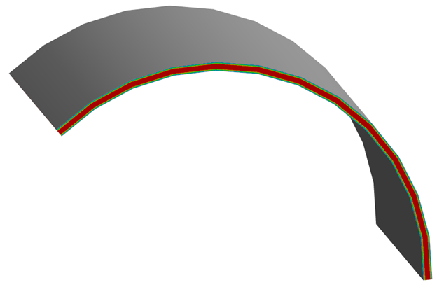
In this workshop attendees will learn how to use ACCS to model the curing of a C-shape composite profile made from carbon fiber prepreg. Completing a thermal simulation of the process yields results such as material state, degree of cure, glass transition temperature, and heat of reaction. From there, a structural analysis of the curing process allows for the prediction of process induced distortions and stresses.
Workshop 2 - C-Shape Profile Fast Cure Simulation
This workshop is nearly identical to the previous workshop with the difference being that the fast solution method is used instead of the full method. This method assumes a uniform temperature distribution and applies to relatively thin (less than 5 mm) composite structures.
Workshop 3 - Tool Compensation
In this workshop users will build on what they learned in the previous workshops to not only predict the composite curing process induced distortions but also compensate for them in the tooling geometry to produce a composite structure that meets the original design specifications. Attendees will also learn how to simulate post-cure trimming operations.
Course Enrollment and Schedule
Ansys Composite Cure Simulation
by Mai Vang, Marketing Director | Jun 27, 2023
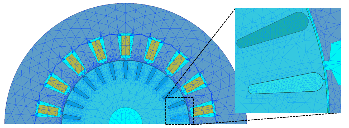
This 1-day course provides an introduction to modeling motors using Ansys RMxprt and Ansys Maxwell.
During the course, students will build hands-on skills by setting up and solving a variety of simulation models during the workshop sections.
Prerequisites for this course are DRD’s Introduction to Maxwell course and practice gaining proficiency with Maxwell. DRD recommends that students who do not have those prerequisites delay attending this course until they attain them. This course does not assume any experience with RMxprt.
Section 1: Geometry Generation
Workshop 2 – Motor Losses
This workshop explores an example induction motor to understand power loss prediction in Maxwell. It will show how to obtain these quantities during postprocessing, how to validate them through checking the power balance, and how to improve simulation accuracy on these results. RMxprt will be used to both analyze the motor and to generate Maxwell 2D and 3D models of the design.
Section 2: Cogging Torque
Workshop 1 – Cogging Torque Calculation
This workshop will discuss how to use ANSYS Maxwell to calculate the cogging torque in an example 3-phase permanent magnet machine. Both a parametric static and pseudo-static transient methodology will be explored.
Section 3: Mesh Operations for Rotating Machines
Workshop 3 – Demagnetization Due to Short Circuit
This workshop will discuss how to use Ansys Maxwell to study the variation of Permanent Magnet Rotating Machine performances due to short circuit and related high value external fields and permanent magnets demagnetization.
Section 4: Motor Power Balance
Workshop 4 – Using the Machine Toolkit on a PMSM Model 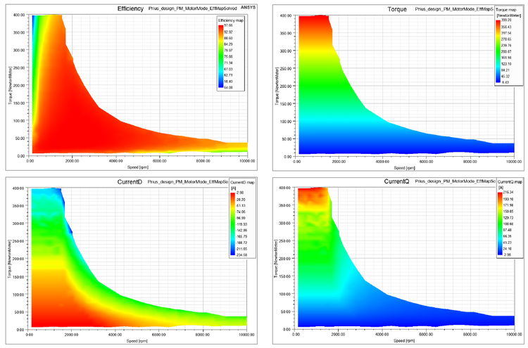
This workshop starts with an existing 3-phase permanent magnet synchronous machine model that’s set up to solve one operating point. The user will then use the Machine Toolkit extension to define the Design of Experiments runs which will populate the full operating space. Output maps such as efficiency, losses from different sources, torque vs. speed, and voltage/current in the d-q frame can be obtained for this design after running the DOE that the toolkit automatically creates.
Section 5: OptiSlang Coupling
Section 6: ECE Equivalent Circuit Extraction
Section 7: Demagnetization
Section 8: Machine Toolkit
Section 9: Inductor Machine Speedup
Course Enrollment and Schedule
Ansys Maxwell Motor Modeling
by Mai Vang, Marketing Director | Jun 27, 2023
This course provides workshops demonstrating the Shooting Bouncing Ray (SBR+) solver and antenna placement, using the ANSYS HFSS environment of the ANSYS Electronics Desktop (AEDT) Suite. This tool is included in the ANSYS HFSS Premium and ANSYS Electronics Enterprise licenses.
The course focuses on utilizing the SBR+ solution design type and performing antenna placement analysis. Within this course, one will analyze the electrical behavior of an antenna near a large 3D component (such as the body of a car) and understand how SBR+ utilizes less computational resources for more efficient simulations. In addition, predicting the coupling between two or more antennas while employing the SBR+ solver and large 3D components is demonstrated.
Most workshops begin with projects where CAD geometry has already been prepared or is drawn in the tool as part of the exercise. DRD encourages students to bring ACIS files with them to the training (preferably from their workplace) if they desire to test their own antenna geometry.
Module 1: Introduction & 3D Component
Workshop 1.1 — PIFA Antenna 3D Component 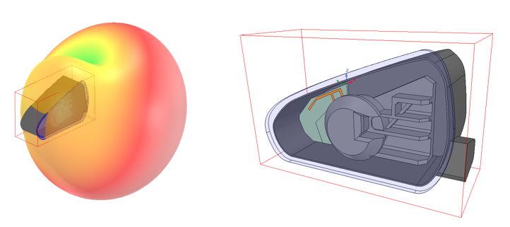
This workshop demonstrates how HFSS can be used to design and analyze an 800 MHz PIFA (planar inverted-F antenna) element, including the chassis that makes up this entire antenna module.
Module 2: Antenna Placement
Workshop 2.1 — SBR+ Platform Integration 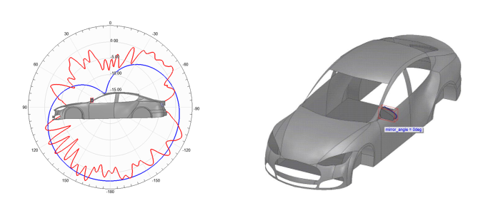
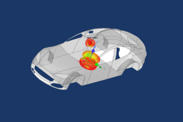
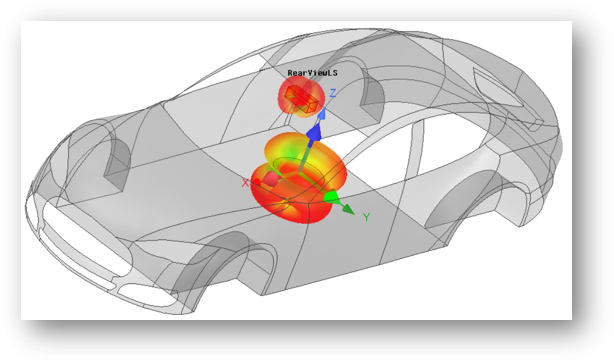
This workshop uses HFSS and SBR+ (Shooting Bouncing Ray) to analyze and predict the performance of an antenna integrated on to an electrically large platform, a car body.
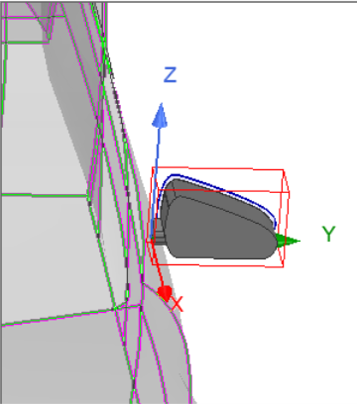
Workshop 2.2 — Side Mirror Near Field Link 
This workshop uses HFSS and SBR+ solution type design to analyze and predict the performance of an antenna linked to a car body.
Module 3: Antenna Coupling
Workshop 3.1 — Far Field Antenna to Antenna Coupling
This workshop demonstrates how an SBR+ design type can be used in HFSS to simulate the coupling between two different antennas.
Module 4: Car Garage Visual Ray Tracing (VRT)
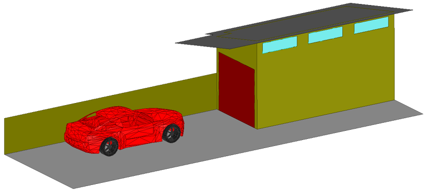
Workshop 4.1 — Vehicle to Home Communication with SBR+
This workshop analyzes coupling between a vehicle mounted antenna and a home Wi-Fi antenna.
Course Enrollment and Schedule
HFSS SBR+ Antenna Placement Design
by Mai Vang, Marketing Director | Jun 23, 2023
This course provides workshops, emphasizing on antennas, using the ANSYS HFSS environment of the ANSYS Electronics Desktop (AEDT) Suite. The general problem addressed is that of the high frequency electromagnetic field and antenna analysis.
The course focuses on the set-up and analysis of antenna simulations via the HFSS user interface. This tool is included in the ANSYS HFSS Premium and ANSYS Electronics Enterprise licenses. Within this interface, one can create CAD geometry of Antennas to analyze the near/far fields, surface currents, impedance, and S-parameters. One can also use the Antenna Design Toolkit (ATK) wizard to create common antenna geometry for ease of simulation design.
Most workshops begin with projects where CAD geometry has already been prepared or is drawn in the tool as part of the exercise. DRD encourages students to bring ACIS files with them to the training (preferably from their workplace) if they desire to test their own antenna geometry.
Module 1: Far and Near Fields
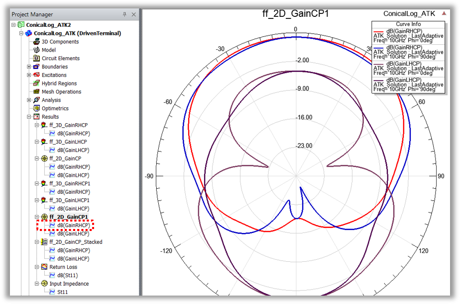
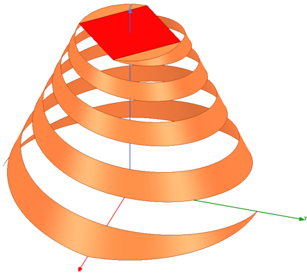
Workshop 1.1 — Conical Spiral Antenna with HFSS Antenna Toolkit
This workshop synthesizes a design for a conical spiral antenna using the ACT Extension HFSS Antenna Toolkit and generates the simulation reports and plots.
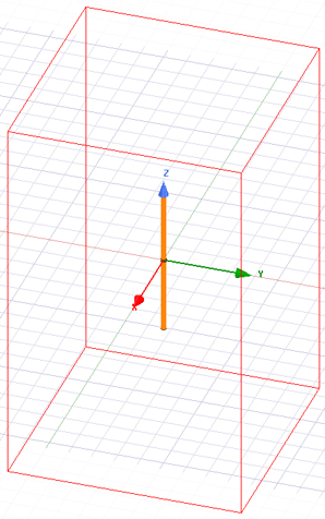
Workshop 1.2 — Dipole Antenna Far Fields
This workshop starts with a new HFSS project and HFSS design. A dipole antenna is chosen from the Component Library as a starting point for the geometry and the excitation.
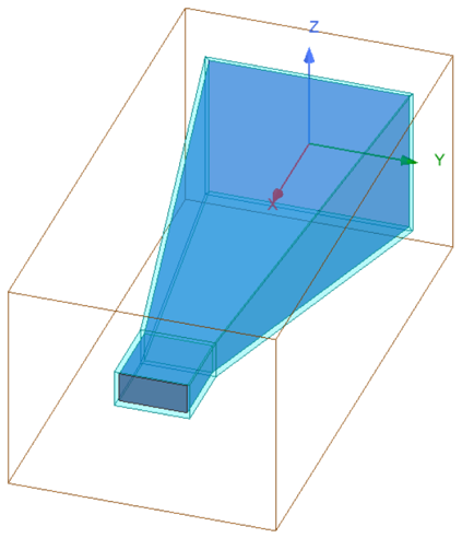
Workshop 1.3 — Horn Antenna Far Field Components
This workshop starts with an HFSS horn design and an incomplete setup. The initial orientation of the horn, relative to the coordinates, has the X-axis at boresight.
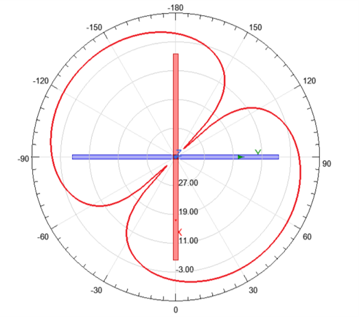
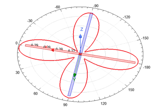
Workshop 1.4 — Crossed Dipole Antenna Near Fields
This workshop starts with two crossed dipole antennas. After initial simulation, and viewing the results, several near field quantities are plotted and exported.
Module 2: Sources and Field Quantities
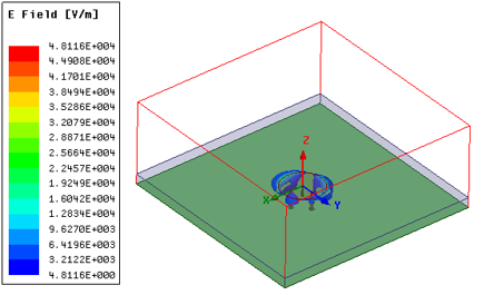
Workshop 2.1 — Crossed Dipole Antenna Sources
This workshop starts with two crossed dipole antennas and demonstrates how to plot far field using a far field infinite sphere setup.
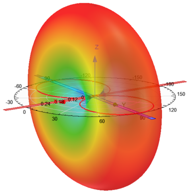
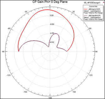
Workshop 2.2 — Circularly Polarized Patch Antenna
This workshop focuses on Antenna post-processing such as radiation patterns and plotting 2D & 3D fields on Antenna geometry.
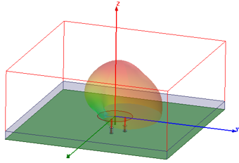
Workshop 2.3 — Circular Polarization Patch Advanced Field Quantities
This advanced workshop evaluates patch antenna S-parameters data, plotted solved fields, and pattern data.
Module 3: Boundaries
Workshop 3.1 — Patch Antenna Open Region Boundaries
This workshop demonstrates two approaches to creating open boundaries and gain insight about both approaches by seeing them applied to the same structure.
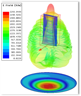
Workshop 3.2 — PIFA Boundaries: ABC PML FE-BI
This workshop demonstrates creating boundaries, such as Absorbing Boundary Condition (ABC), Perfectly Match Layer (PML), and Finite Element – Boundary Integral (FE-BI) for a Planar Inverted – F Antenna.
Module 4: Dynamic Link
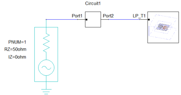
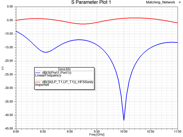
Workshop 4.1 — Dynamic Link
This workshop demonstrates how to dynamically link an HFSS design into a circuit simulation, use the Smith Tool in circuit design to match the antenna using lumped components, and push excitations from the circuit design to the HFSS design.
Module 5: Optimization
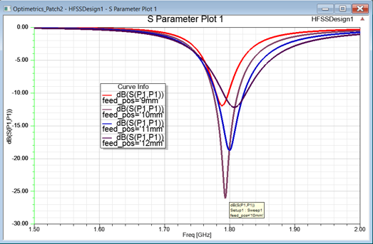
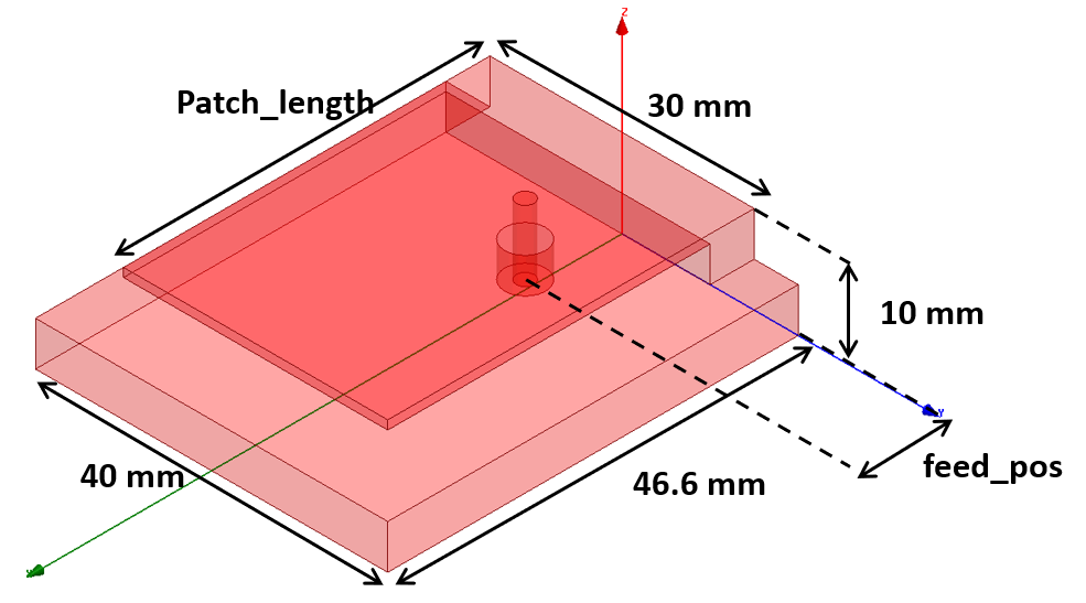
Workshop 5.1 — Antenna Optimetrics
This workshop demonstrates how to set up a parametric study, optimize, and simulate the Analytic Derivatives of a probe-fed patch antenna.
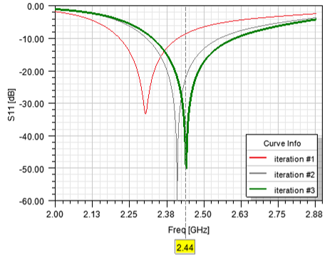
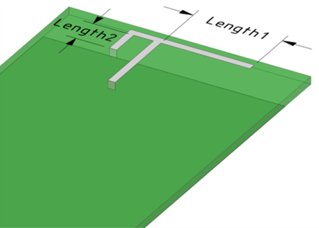
Workshop 5.2 — OptiSLang Derivatives Optimization of PIFA
This workshop demonstrates the derivative-based optimizer to optimize a planar inverted-F antenna (PIFA) design.
Module 6: HFSS Integral Equation (IE)
Workshop 6.1 — HFSS IE Blade Antenna
This workshop demonstrates how to set up, simulate, and analyze an airplane-mounted plane (blade) antenna using the Integral Equation (IE) solver.
Module 7: Formulations
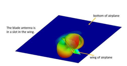
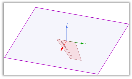
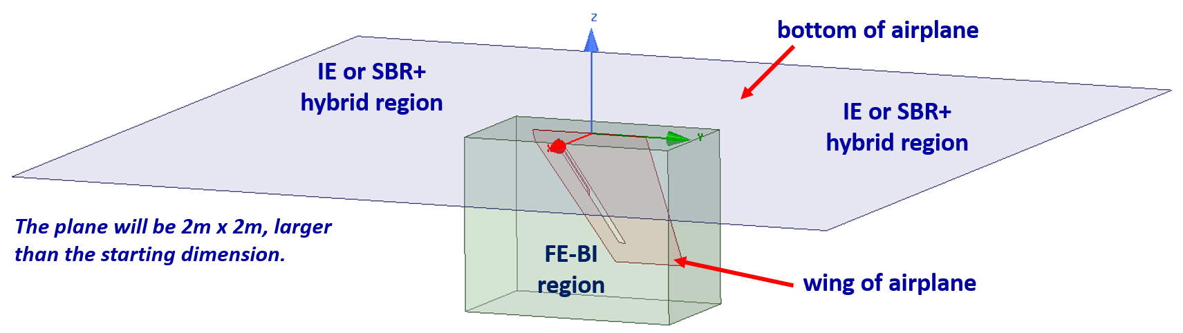
Workshop 7.1 — FE-BI Blade Antenna
This workshop sets up, simulates, and compares simulations of the airplane-wing mounted blade antenna. The large, flat geometry, representing an airplane fuselage, is simulated with both IE (Integral Equation) and SBR+ (Shooting Bouncing Rays).
Module 8: Hybrid Regions
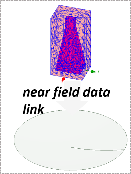
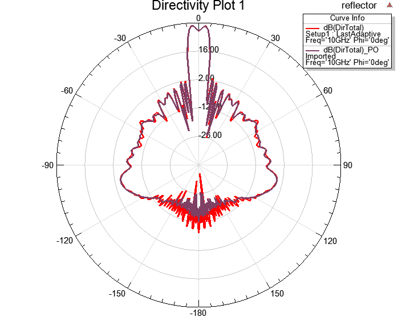
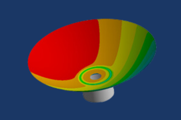
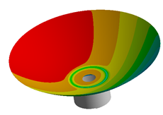
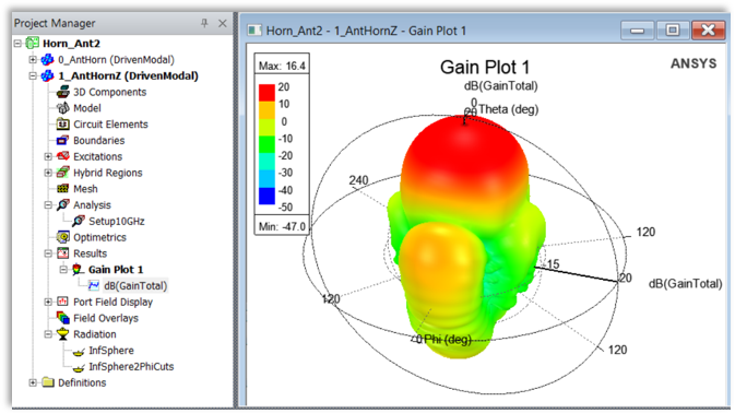
Workshop 8.1 — Data Linked Simulation of a Reflector Antenna
This workshop will demonstrate near field simulation results from a horn antenna and will feed a reflector antenna through a data link while also comparing the result of the Integral Equation (IE) and Physical Optics (PO) solvers.
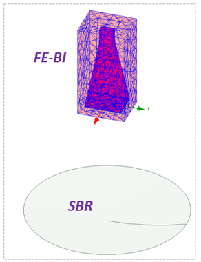
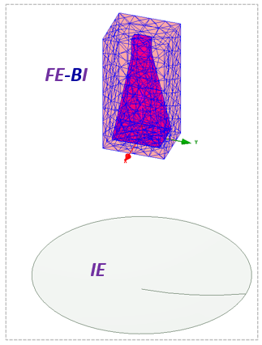
Workshop 8.2 — Hybrid FEM-FEBI Simulation of a Reflector Antenna
Workshop 8.3 — Hybrid FEM-FEBI Antenna Placement Study
This workshop will demonstrate radiation field results when using a Finite Element-Boundary Integral (FE-BI) region on the horn antenna and use a Integral Equation (IE) solver on the reflector.
Course Enrollment and Schedule
Ansys HFSS Antenna Design
by Mai Vang, Marketing Director | Jun 22, 2023
This course provides an introduction to thermal modeling capabilities in Ansys Mechanical. Ansys Mechanical handles conduction and radiation heat transfer including calculation of view factors for surface-to-surface radiation. Mechanical also handles convection heat transfer, primarily as a boundary condition based on a heat transfer coefficient and a bulk temperature. Material properties and heat transfer coefficients can be temperature-dependent.
This course is entirely workshop-based with no dedicated lecture component and takes place over a single day. The emphasis is placed on the creation and solution of practical thermal analyses rather than detailed presentation of heat transfer theory. The goal is to introduce the most important tools for heat transfer analysis and to show best practices for modeling common heat transfer problem types.
This is an advanced course, and attendees are expected to be comfortable with the basics of Ansys Workbench and Mechanical. It is recommended that attendees complete DRD’s Introduction to Ansys Mechanical course prior to attending this course. Engineers already proficient with Ansys Mechanical also have the course prerequisite.
Course Requirements:
Ansys Version used to create course content: 2023 R1
Ansys Version DRD instructor will use for the course: 2023 R1
Ansys Version(s) students may use for the course: 2023 R1
Registration for all classes will close 5 business days in advance of the class date.
Learn more: Agenda + Course Description
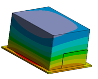
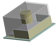
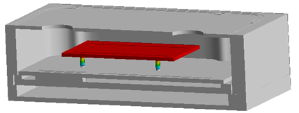
Workshop 1 – Hazardous Material Cabinet Subjected to Steady Temperature Load
In this workshop we model steady-state heat transfer in a hazardous material enclosure. This simplified analysis incorporates convection with the environment as well as internal conduction in a multi-part assembly. We introduce techniques for estimating and assigning convection coefficients based on the temperature difference between the fluid and the convection surface. Temperature-dependent material properties are created and assigned.
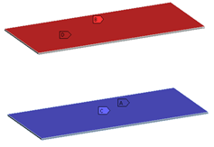
Workshop 2 – Parallel Plates with Radiation Heat Transfer
In this workshop we introduce radiation heat transfer. We compare the results from using radiation boundary conditions in FEA with hand calculations for a case of two parallel plates of known temperature.
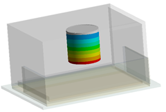
Workshop 3 – Hazardous Material Cabinet Thermal Analysis with Radiation
In this workshop we continue Workshop 1 by adding radiation to the model, which allows heat to be transferred to and from an internal cylinder containing hazardous materials.
Workshop 4 – Hazardous Material Cabinet Subjected to Fire
In this workshop we continue the analysis on the hazardous material cabinet, this time performing a transient thermal analysis in order to observe the temperatures of the materials after the exterior is exposed to fire.
Workshop 5 – Antenna Subjected to Solar Loads and Thermal Stress
In this workshop we model solar radiation using an MAPDL Commands object. We also defeature components that are not important to a thermal analysis, then map the results from the defeatured thermal model onto a full-featured structural model in order to perform a thermal stress analysis.
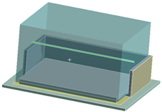
Workshop 6 – Heat Transfer Analysis of an Electronics Enclosure
In this workshop we demonstrate two uses of contact resistance: accounting for imperfect contact and modeling thin bodies with a specified resistance in the thickness direction.
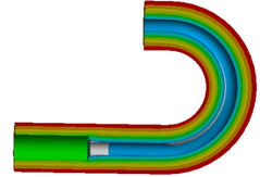
Workshop 7 – Effect of Exhaust Radiation Shield on Windshield
In this workshop we examine how a radiation shield surrounding a high-temperature exhaust pipe affects a nearby windshield.
Workshop 8 – Thermal Analysis of Fuel Injection Nozzle with Fluid Flow
In this workshop we use Thermal Fluid elements to model fluid flow through a nozzle. The thermal analysis accounts for convection heat transfer between the fluid and the nozzle, as well as a specified mass flow rate of the fluid.
Workshop 9 – Heat Transfer in a Cabinet with Internal Convection
This workshop is designed to provide students with practice modeling assemblies. We read the assembly into Mechanical and perform static stress analysis using default bonded contact to hold the parts together. We then use model branching to make a new version of the model, which has no separation contact instead of bonded contact for some of the connections, and we compare the behavior of the models with bonded and no separation contact in the connections.
Workshop A – Radiation Heat Transfer from Exhaust Pipe to Gas Tank
In this appendix workshop, we give students the opportunity to practice setting up a heat transfer model without detailed instructions. The goal is to evaluate whether radiation from the exhaust pipe will bring the fuel tank to an unsafe temperature.
Course Enrollment and Schedule
Ansys Mechanical Thermal Simulation


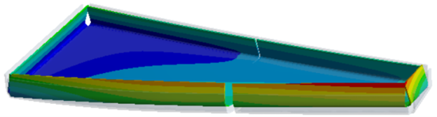 In this workshop users will build on what they learned in the previous workshops to not only predict the composite curing process induced distortions but also compensate for them in the tooling geometry to produce a composite structure that meets the original design specifications. Attendees will also learn how to simulate post-cure trimming operations.


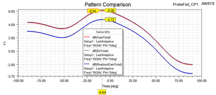
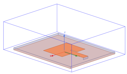
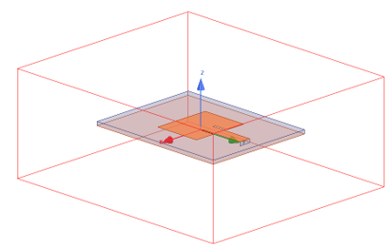
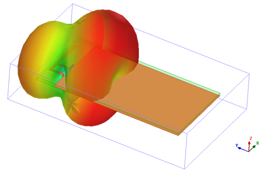


 This workshop demonstrates how to set up a parametric study, optimize, and simulate the Analytic Derivatives of a probe-fed patch antenna.