by Mai Vang, Marketing Director | Jul 30, 2023
This course provides an introduction to the HFSS environment of the Ansys Electronics Desktop (AEDT) Suite. The general problem addressed is that of the high frequency electromagnetic field. The course focuses on the use of the HFSS user interface. This tool is included in the Ansys HFSS Premium and ANSYS Electronics Enterprise licenses. Within this interface, one can create CAD geometry, import CAD geometry, assign material properties, apply excitations, perform solutions, and review analysis results.
The course presents solutions to general electromagnetic problems encountered by most antenna/RF designers. Approaches for calculating characteristic impedance, S-parameters, electric/magnetic fields, and near/far fields are covered. Most workshops begin with projects where CAD geometry has already been prepared or is drawn in the tool as part of the exercise. DRD encourages students to bring ACIS files with them to the training (preferably from their workplace) if they desire to test their own geometry.
Module 1: Overview of HFSS
Workshop 1.1 — Band Pass Filter Simulation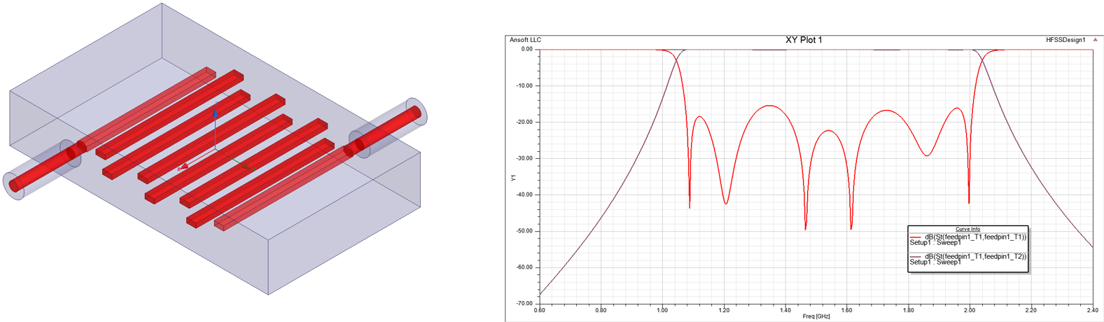
This workshop introduces the HFSS application via a previously set up simulation of a microwave band pass filter.
Module 2: Boundaries and Simulation Space
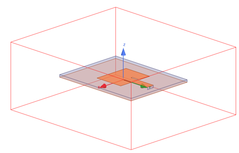
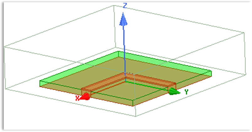
Workshop 2.1 — Patch Antenna Open Region
This workshop starts with a project that does not yet have the open region boundary assigned. The user will create both the region air box and the radiation boundary assignment.
Workshop 2.2 — Coax Bend Finite Conductivity Boundary
This workshop demonstrates how to change the default PEC boundary on an HFSS coaxial bend model to a finite conductivity boundary.
Module 3: HFSS FEM Solution Setup
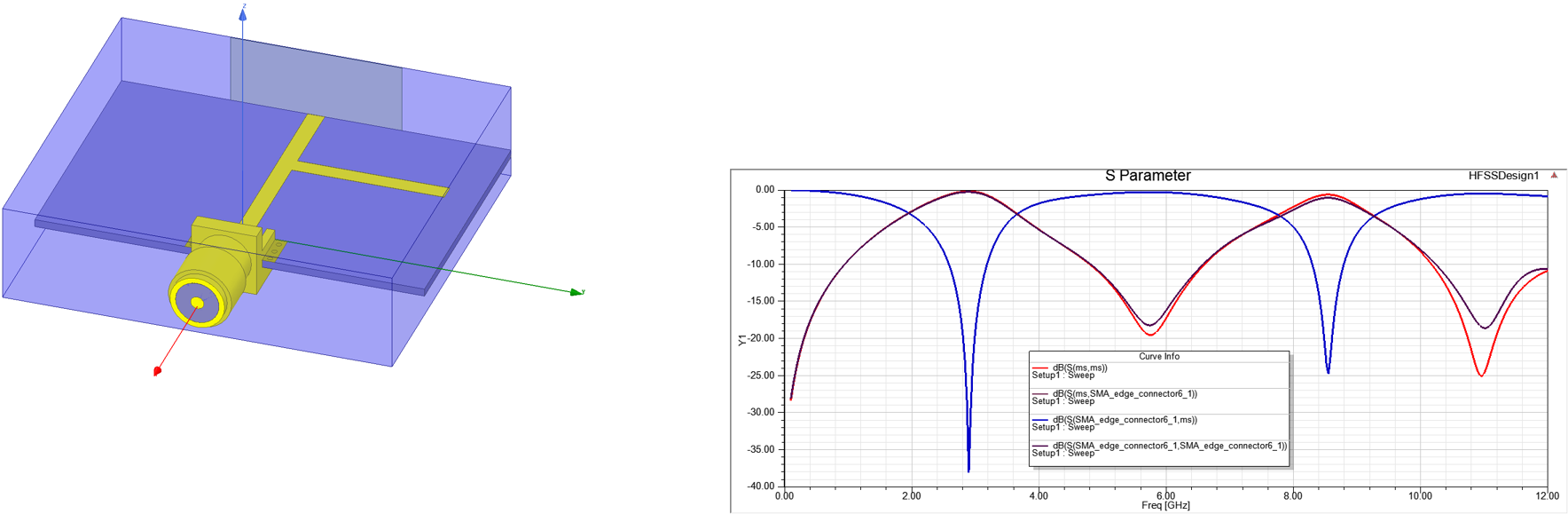
Workshop 3.1 — SMA Stub Auto Solution Setup
This workshop demonstrates a HF simulation of an SMA Coax Microstrip Stub and the resulting S-parameters.
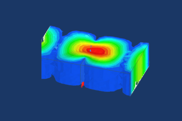
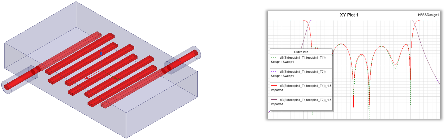
Workshop 3.2 — Band Pass Filter Broadband Mesh
This workshop demonstrates the broadband mesh capabilities of HFSS on a microwave filter simulation.
Module 4: Simulation Post Processing
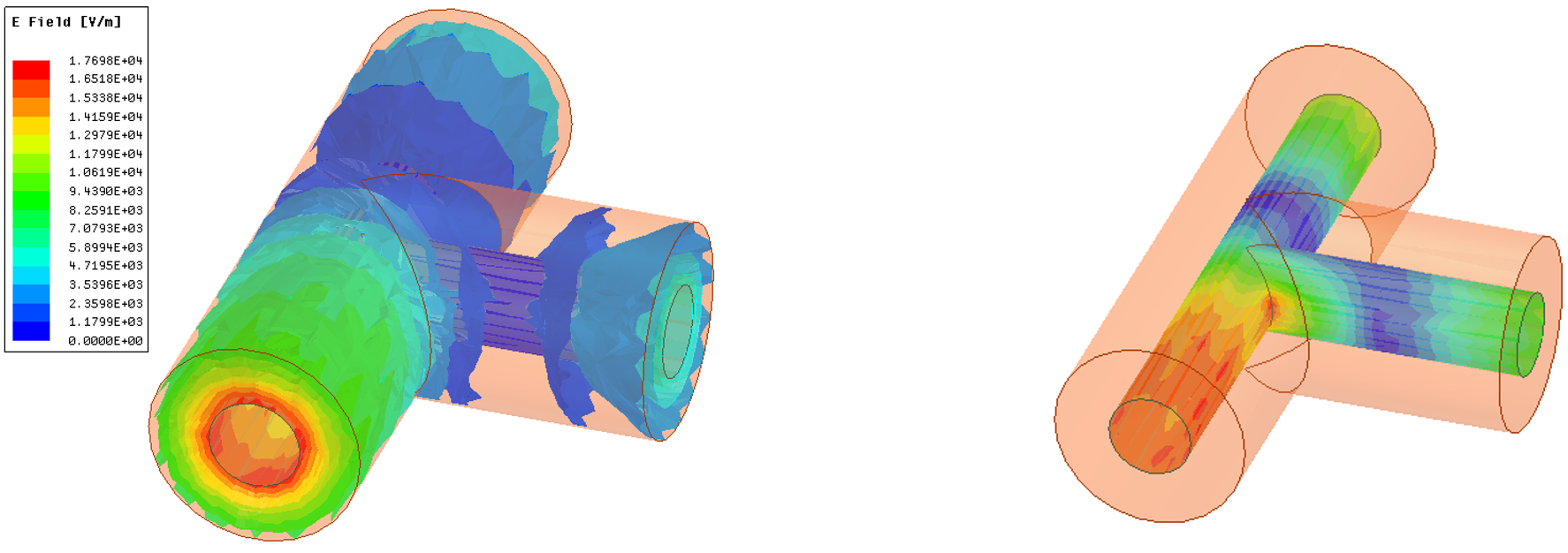
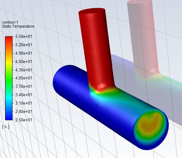
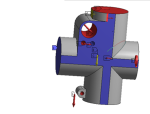
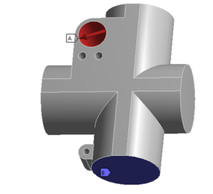
Workshop 4.1 — Coax Tee S-Parameters and Fields
This workshop on HFSS post-processing focuses on rectangular plots of S-parameters and field plots on a simple coaxial “T” geometry.
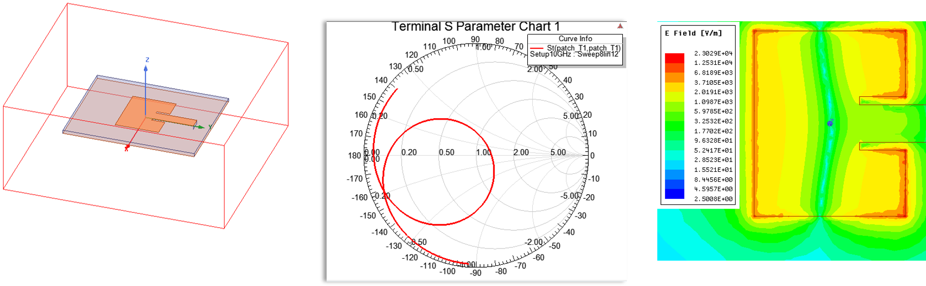
Workshop 4.2 — Patch Antenna Smith Chart and Field Plots
This workshop demonstrates plotting the S-parameters of a patch antenna in Smith Chart format, as well as plotting electric fields on a surface.
Module 5: Geometry Construction
Workshop 5.1 — Microstrip Bend Geometry Construction
This workshop demonstrates creating parameterized HFSS geometry from scratch. The geometry created is a microstrip transmission line with a right-angle bend.
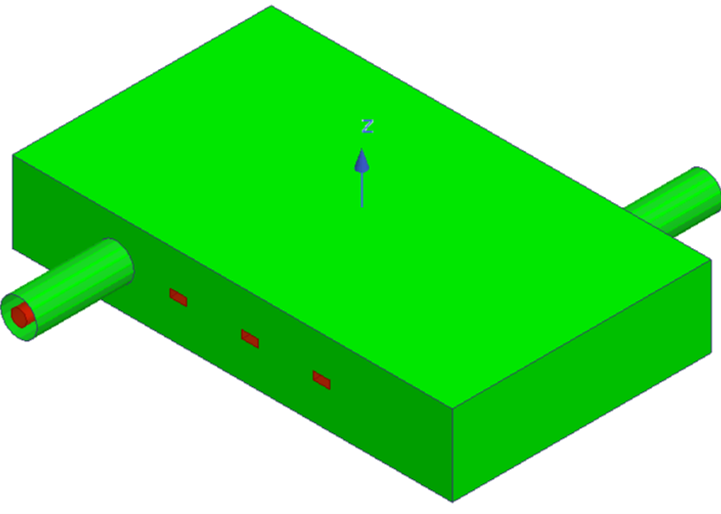
Workshop 5.2 — WR 90 Waveguide Filter Geometry Construction
This workshop demonstrates creating parameterized geometry for a WR 90 X-band waveguide.
Workshop 5.3 — Assigning a Finite Conductivity Boundary to Band Pass Filter
This workshop changes the default PEC boundary on a band pass filter example to a finite conductivity with aluminum properties.
Module 6: HFSS Lumped and Wave Port Basics
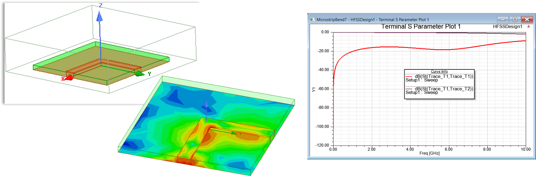
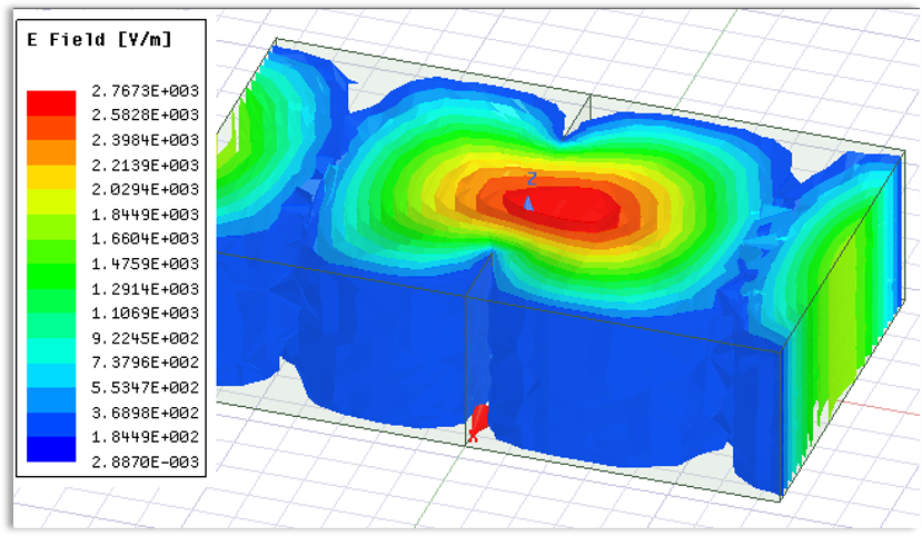
Workshop 6.1 — Microstrip Bend Lumped Ports Simulation
This workshop starts with a microstrip transmission line with a right-angle bend built in the geometry and demonstrates creating lumped ports along with calculating the resulting S-parameters.
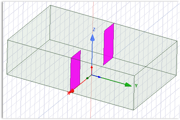
Workshop 6.2 — Waveguide Wave Ports Simulation
This workshop demonstrates exciting a wave guide with wave ports and post processing the results.
Module 7: Optimetrics and High-Performance Computing (HPC)
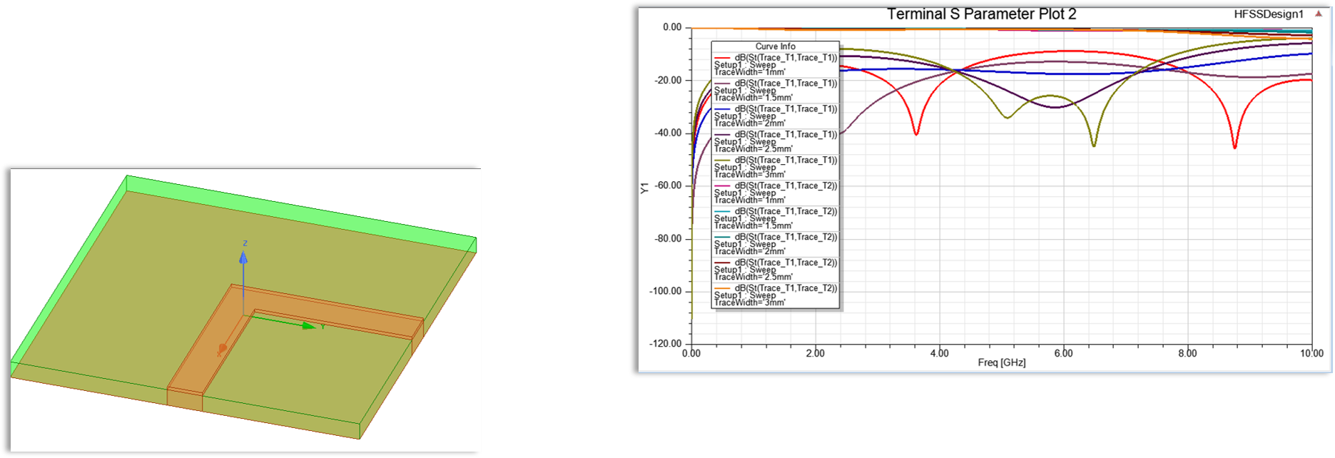
Workshop 7.1 — Microstrip Bend Parameter Sweep
This workshop demonstrates a parameter sweep and tuning exercise on a microstrip bend.
Workshop 8.1 — 30mm Coax Construction and Simulation
This workshop is an unscripted exercise to practice HFSS concepts with no detailed instructions. Only a general outline of the problem is provided.
Course Enrollment and Schedule
Introduction to Ansys HFSS
by Mai Vang, Marketing Director | Jul 30, 2023
This course provides an introduction to conducting CFD simulations in Ansys CFD.
The course devotes little time to CFD theory and focuses on practical use of the software through both lectures and workshops that demonstrate practical problems. Workshops build in difficulty throughout the course and develop skills in setup, solving, and postprocessing models in Fluent.
Early workshops create geometry from scratch or import CAD geometry as starting points. This allows students to build skills with meshing and geometry preparation. Latter workshops utilize pre-generated mesh files allowing for more complex problems to be undertaken during class time.
DRD encourages the students to be ready to discuss their application for Fluent with the instructor so that we can best tailor the training to each student.
DRD conducts this course over two days. Students will receive all training materials to take home and reference later.
Chapter 1 – SpaceClaim User Interface, Basic Operations, and Creating Geometry
Workshop 1.1 – SpaceClaim Basics
In this workshop we introduce Ansys SpaceClaim and use it to extract a fluid volume from a mixing tee.
Workshop 1.2 – Geometry Repair using SpaceClaim
This workshop introduces the use of automated repair tools in SpaceClaim.
Workshop 1.3 – Creating a Mixing Tee from Scratch
This workshop demonstrates creating geometry from Scratch in SpaceClaim.
Workshop 1.4 – Creating Named Selections and Bodies of Influence in SpaceClaim
This workshop introduces creation of named selections and bodies of influence. Shared topology considerations for bodies of influence are also discussed.
Chapter 2 – CFD Overview
Workshop 2 – Mixing Hot and Cold Streams in a Mixing Tee
This workshop covers the creation of a model in which two air streams at different temperatures are mixed together. The mixing uniformity is analyzed.
Chapter 3 – Watertight Geometry Workflow Overview and Surface Meshing
Workshop 3 – Meshing of a Static Mixing Device
This workshop demonstrates meshing a solid geometry using capping within the Fluent Meshing Watertight Workflow.
Chapter 4 – Geometry Description and Volume Meshing
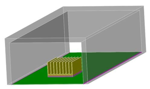
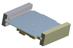
Workshop 4 – Meshing of a PCB and Heatsink
This workshop covers meshing of a heat producing electrical component on a circuit board. The board, component, heatsink, and surrounding air are meshed in preparation for solving.
Chapter 5 – Solution Mode User Interface
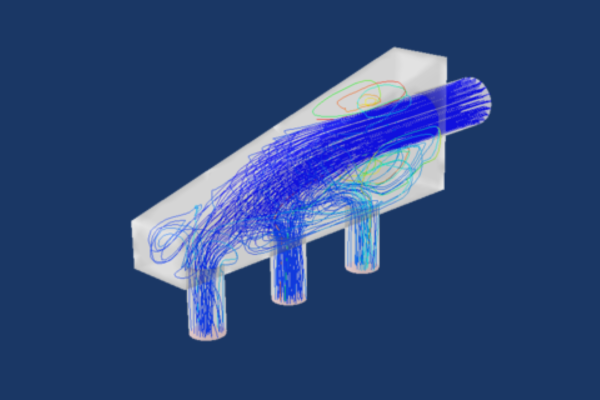
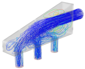
Workshop 5 – Flow Distribution in an Air Manifold
This workshop demonstrates how to conduct a simple flow analysis in Fluent. Relative flow rates between the outlets are also examined.
Chapter 6 – Physics Tab
Workshop 6 – Meshing and Solving Using Zero Thickness Baffles
A duct with turning vanes is meshed in Fluent Meshing and solved. Proper meshing of zero thickness baffles is demonstrated.
Chapter 7 – Results Tab
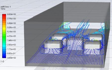
Workshop 7 – Flow Over Heated Obstacles
This workshop introduces heat transfer via wall boundary conditions and utilizes symmetry to speed up computation of the solution.
Chapter 8 – Solution Tab
Workshop 8 – Solver Options and Settings
The mixing tee model is reexamined using various solver settings to see how they affect convergence behavior and result quantities.
Chapter 9 – Best Practices
Workshop 9 – Turbulent Flow Past a Backward Facing Step
Flow separation on a backward facing step is analyzed. The effect of including an accurate inlet velocity profile is also explored.
Chapter 10 – Turbulence
Workshop 10 – Electronics Cooling with Natural Convection and Radiation
This workshop covers the conjugate heat transfer analysis of a heated chip and heatsink undergoing natural convection. Surface-to-surface radiation is also examined.
Chapter 11 – Heat Transfer
Chapter 12 – Transient Simulation
Course Enrollment and Schedule
Introduction to Ansys Fluent
by Andy Bax | Jul 30, 2023
This course provides an introduction to the Ansys Mechanical Environment of the Ansys software product suite.
The course focuses on use of the Mechanical user interface, which is included in Ansys Mechanical Pro, Ansys Mechanical Premium, and Ansys Mechanical Enterprise. Within this interface you read CAD geometry, assign material properties, apply loads and boundary conditions, define mesh controls, perform solutions, review analysis results, and generate an automatic html report.
The course devotes some time to theory and concepts at a very basic and practical level. These topics include finite element concepts, solutions of simultaneous equations, and contact models. These portions of the course emphasize practical theory concepts, which engineers need to understand in order to do finite element analysis.
Chapter 1 - Overview of Mechanical
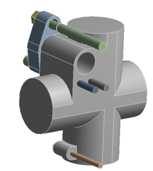
Workshop 1 – Static Stress Analysis of a Fluid Connector
In this workshop we expose the user to the Ansys Workbench and Mechanical interfaces and perform a simple static stress analysis on the fluid connector. Basic file management is discussed as well.
Chapter 2 - General Overview of FEA
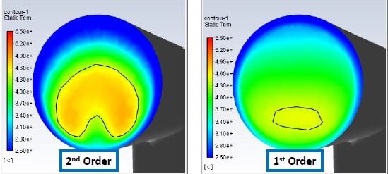
Workshop 2a – Element Types and Physical Behavior
This workshop demonstrates how to control creation of lower order versus higher order elements and tetrahedron versus brick elements in Mechanical. It also provides students the opportunity to compare solution accuracy and computational resources for models with lower and higher elements using the Mechanical solution information object.
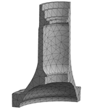
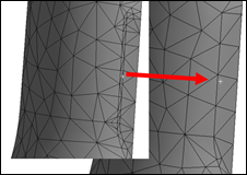
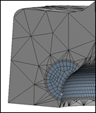
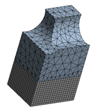
Workshops 2b – 2h. Mesh Controls on a Casting
This set of workshops demonstrate how to use some of the meshing techniques available in Mechanical to obtain accurate stresses with pinch controls, Multizone, Inflation, and Sphere of Influence methods .
Chapter 3 - Material Properties
Workshop 3 – Assigning Material Properties to Parts in a PWB Assembly
This workshop uses various WB techniques to assign material properties. The WB Engineering Data Module is discussed in detail.
Chapter 4 - Loads and Boundary Conditions for Structural Analysis
Workshop 4 – Stress Analysis of a Pump Fluid End With Multiple Load Conditions
This workshop exposes all of the various structural loading options available within Mechanical.
Chapter 5 - Solution Options to Static Structural Analysis
Workshop 5 – Stress Analysis of a Pump Fluid End Using Direct and Iterative Solvers
We start the solution with an assembly and suppress all of the parts, except one for analysis. We use mapped meshing to set up the mesh. We use solution options to control which solver Mechanical uses for a static solution, direct or iterative. We use the solution information object to monitor the solution and to determine which solver is faster. For the iterative solve we use a preprocessing command object to set the solution accuracy. We turn the weak spring option off and on to determine the effect of weak springs on the solution.
Chapter 6 - Evaluation of Analysis Results
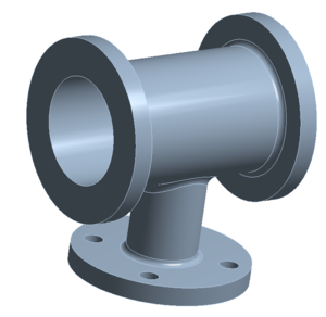
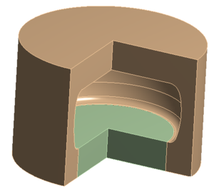
Workshop 6a – Stress Analysis of a Flanged Tube and Check of Results
The primary purpose of this workshop is to provide students the opportunity to check the results of the finite element model using hand calculations based on closed form solutions. We use symmetry boundary conditions to perform analysis on a quarter model of the flanged tube. We define a local cylindrical coordinate system and then use it to calculate axial, radial, and hoop component stresses. Finally, we compare the finite element model component stresses with stresses calculated using closed form equations for thin and thick walled pressure vessels. Students discuss with the instructor the correlation between the finite element and hand calculated stresses.
Workshop 6b – Postprocessing Options, Introduction to Scoping and Convergence
This workshop covers the extensive options available for results post-processing within Ansys Mechanical including cut planes, vector plots, legend manipulation, result display scaling, etc. We also get a first look at scoping of results and cover the concept of mesh convergence.
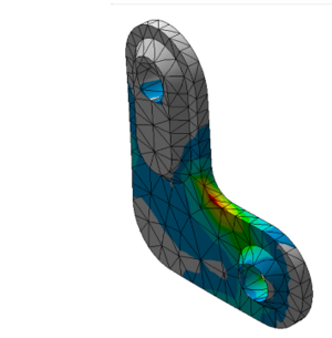
Chapter 7 - Evaluation of Local Stresses
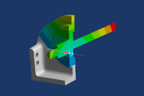
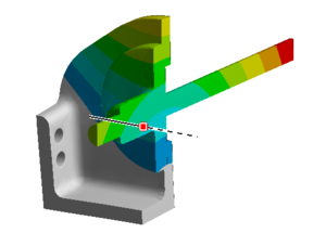
Workshop 7 – Stress Analysis of a Mechanical Link Using Scoping and Convergence
The focus of this workshop is use of scoping and convergence to evaluate local stresses. We start the workshop by doing stress analysis on a version of the link, which has a sharp corner, and students refine the mesh at the sharp corner to discover first hand the behavior of a stress singularity. Using model branching students add to the project a version of the link, which has a fillet where the sharp corner was present in the previous version. Students define a scoped stress object for stresses in the fillet and then use convergence to determine the stress to an accuracy of 2%.
Chapter 8 - Modal Analysis
Workshop 8 – Modal Analysis of an Alternator Bracket with and without Prestress
In this workshop we set up a model of an alternator bracket for normal modes analysis. We model the alternator attached to the bracket as a rigid point mass and monitor the change in natural frequencies and mode shapes as we change it to a deformable point mass. We also add standard earth gravity and note that Mechanical takes into account prestress effects if structural loads are present while performing a normal modes analysis.
Chapter 9 - Modeling Assemblies with Contacts
Workshop 9 – Stress Analysis of a Platform Assembly
This workshop is designed to provide students with practice modeling assemblies. We read the assembly into Mechanical and perform static stress analysis using default bonded contact to hold the parts together. We then use model branching to make a new version of the model, which has no separation contact instead of bonded contact for some of the connections, and we compare the behavior of the models with bonded and no separation contact in the connections.
Chapter 10 - Modeling Assemblies with Joints
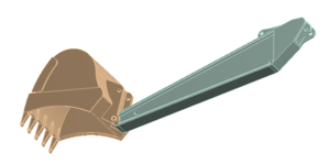
Workshop 10a – Modeling Joints in a Backhoe Lift Bucket Assembly
This workshop is focused on connecting parts together with a sample of the many joint types available in Mechanical. It explores the use of the Joint Configure to preview the possible motion of the jointed mechanism, as well as the Redundancy Analysis tool to verify the joints are constraining the motion as desired. Also, it uses the ability to specify parts as rigid instead of flexible to simplify the model.
Workshop 10b – Modeling Joints in a Backhoe Assembly with a Single Hydraulic Cylinder
This workshop builds on the skills developed in the previous workshop by setting up joints on a more complex model. With the higher complexity of the mechanism analyzed in this workshop comes a higher possibility of mistakes, so this workshop focuses on best practices that will aid in building up the set of joints incrementally while verifying the joints at each step of the process.
Chapter 11 - Rigid Body Motion in Static Solutions
Workshop 11 – Stress Analysis of a Pipe and Plate Assembly with Rigid Body Motion
This workshop teaches the user to identify and fix locations in a model that may have rigid body motion due to contact regions that are not correctly defined. We also show the usefulness of a Modal analysis in determining rigid body motion in a static model; rigid body motion causes zero frequency modes in a normal modes analysis.
Chapter 12 - Interaction with CAD
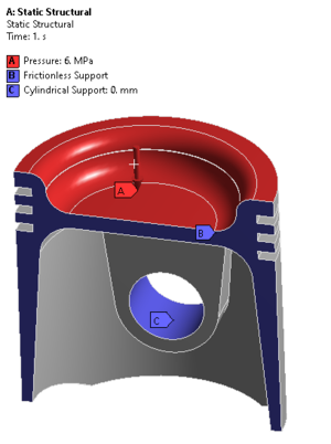
Workshop 12 – CAD Parameter Associativity of a Piston
The purpose of this workshop is to demonstrate associativity between CAD software, Workbench, SpaceClaim, and Mechanical. The starting point for this workshop is a parametric model in SpaceClaim format. SpaceClaim functions as the ‘CAD’ system for this workshop; the same principles apply to CAD packages. We transfer the model to Ansys Mechanical, set up and solve the model in a simple stress analysis. We then make changes to the geometry using SpaceClaim, update the model in Mechanical and re-solve. We demonstrate the usefulness of the Design of Experiments functionality within Workbench.
Workshop A: Thermal-Stress Analysis of a Heat Exchanger
Workshop A: Thermal-Stress Analysis of a Heat Exchanger
A first look at performing a thermal-stress analysis of a heat exchanger. The user is introduced to thermal loads, convection and temperature, and the model is solve. An energy balance is performed using the temperature reaction loads. Following this, the temperature profile of the heat exchanger is fed into a structural analysis through the Workbench project schematic and a simple structural analysis is performed.
Workshop B: Ansys Mechanical Integration with Ansys MAPDL (or Ansys Classic)
Workshop B: Ansys Mechanical Integration with Ansys MAPDL (or Ansys Classic)
This workshop exposes the user to the integration of Mechanical with MAPDL, or Ansys Classic. The students create named selections within Mechanical as well as command objects and then transfer the model into MAPDL. The student explores using MAPDL for object selections, defining loads and solving the model. This workshop is a first look at using MAPDL commands to augment an Ansys Mechanical analysis.
Workshop B: Ansys Mechanical Integration with Ansys MAPDL (or Ansys Classic)
Workshop B: Ansys Mechanical Integration with Ansys MAPDL (or Ansys Classic)
This workshop exposes the user to the integration of Mechanical with MAPDL, or Ansys Classic. The students create named selections within Mechanical as well as command objects and then transfer the model into MAPDL. The student explores using MAPDL for object selections, defining loads and solving the model. This workshop is a first look at using MAPDL commands to augment an Ansys Mechanical analysis.
Course Enrollment and Schedule
Introduction to Ansys Mechanical
by Mai Vang, Marketing Director | Jul 27, 2023
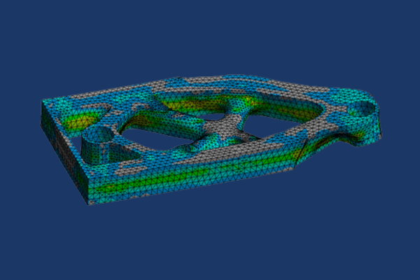
Revolutionary manufacturing techniques are making Topology Optimization a relevant design tool. Results that were previously theoretically correct but impractical to manufacture are now becoming more feasible as advances in 3D printing make Topology Optimization solutions manufacturable.
Ansys offers a full range of products that enable simulation of the entire workflow from Topology Optimization using Ansys Mechanical and faceted geometry cleanup using SpaceClaim to part orientation and support creation using Additive Prep and finally simulation of the Additive Manufacturing process using Workbench Additive.
This 1-day course will focus on Topology Optimization, faceted geometry cleanup, and metal Additive Manufacturing process simulation using Ansys Workbench Additive.
Module 1 - Topology Optimization Basics
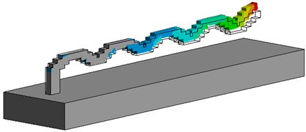
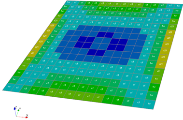
Workshop 1 — Michell Structure
This workshop demonstrates some of the basic capabilities of Topology Optimization to produce an optimized material configuration for the given Structural load case. The result is very similar to the optimum shape that was theorized by Australian Mechanical Engineer, A. G. M. Michell in the early 20th century
Module 2 – Basic Geometry Cleanup in SpaceClaim
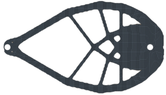
Workshop 2 — Optimized Geometry Cleanup with Extract and Fit Curve Tools
This workshop discusses the various postprocessing options within Ansys Workbench LS-DYNA involving global energy balance, ASCII time history output of contact forces, boundary condition reaction forces, etc. This workshop demonstrates some of the automated tools that can be used to clean up STL geometry from Topology Optimization analysis. Extract Curves and Fit Curves provide easy options for taking non-CAD geometry, which is commonly dirty surfaces, and turning it into smooth CAD surfaces.
Module 3 – Additive Manufacturing Process Simulation in Workbench
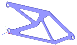
Workshop 3 — Optimized Geometry Cleanup with Automated Facet Tools
This workshop demonstrates some of the automated tools that can be used to clean up STL geometry from Topology Optimization analysis. Basic faceted geometry conversion, curve extraction, and curve fitting are used to create CAD geometry from STL geometry. A special meshing technique is then used to smooth over any faceted surfaces in Ansys Mechanical.
Module 4 – Full Workflow from Topology Optimization to Additive Manufacturing
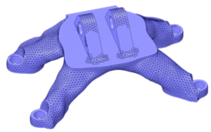
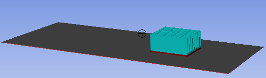
Workshop 4 — Setting up a 3D Print Process Simulation
This workshop uses a very basic geometry to demonstrate how to set up and solve an Additive Manufacturing simulation using ANSYS Workbench Additive. This involves solving a Transient Thermal analysis to calculate the global temperature history of the process and then passing that data into a Static Structural analysis to solve for stresses, deformations, and other Structural results.
Course Enrollment and Schedule
Ansys Topology Optimization and Metal Additive Manufacturing
by Mai Vang, Marketing Director | Jul 21, 2023
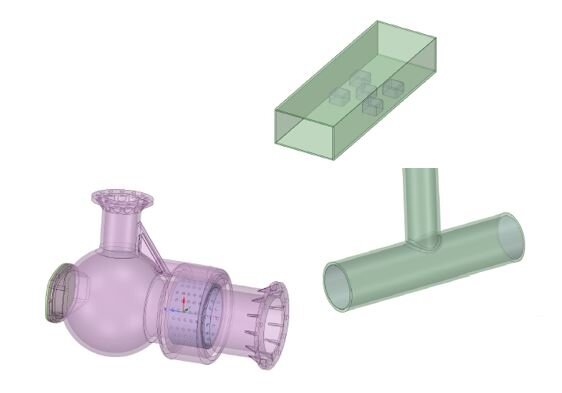
This course provides an introduction to meshing models for Fluent using Workbench Meshing. Fluent Meshing is the preferred tool for the majority of models as it will be able to provide the most efficient meshes on the most complex geometry with the least amount of model prep. However, there are unique scenarios where Workbench Meshing can be used to provide highly sculpted meshes to meet demanding requirements, such as non-Cartesian aligned hexahedral elements (cyclones) or layered elements for modelling 1DOF motion (moving valves). Pure hexahedral and hybrid hexahedral/tetrahedral meshes can provide significant benefits in solution speed and accuracy over unstructured polyhedral or tetrahedral meshes in these scenarios.
Students will focus on completing workshops that build in difficulty throughout the course. Key skills related to fluid volume creation, decomposing geometry in SpaceClaim, and setup of mesh controls in Workbench Meshing will be discussed and practiced.
DRD’s Introduction to Ansys Fluent course is a prerequisite to this course.
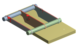
Workshop 1 - Plunger Box
This workshop introduces the basics of geometry preparation for Workbench Meshing along with general purpose tetrahedral meshing with inflation.
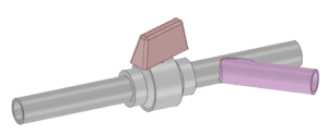
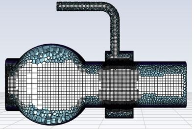
Workshop 2 – Ball Valve
This workshop introduces swept hexahedral meshing alongside the concept of multibody parts that allow for conformal meshes with different element shapes.
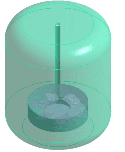
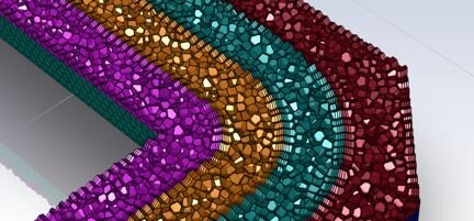
Workshop 3 – Mixing Tank
This workshop presents slicing strategies to maximize hexahedral elements in cylindrically dominated geometry as well as utilizing selective non-conformal meshing.
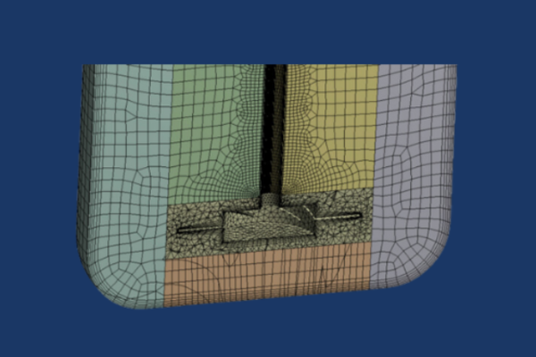
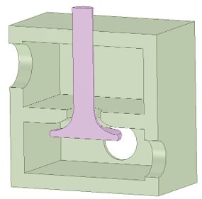
Workshop 3 – Solenoid Valve
This workshop demonstrates recommended meshing strategies for motions containing single degree of freedom motion, including slicing, selectively shared topology, named selection management, and meshing order.
Course Enrollment and Schedule
Workbench Meshing for Ansys Fluent


 Workshop 1 – Static Stress Analysis of a Fluid Connector
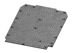


 Workshop B: Ansys Mechanical Integration with Ansys MAPDL (or Ansys Classic)