Occasionally it may be a requirement to report average values of stress or strain from an ANSYS Mechanical analysis. There are tricks to do this either for a group of nodes/elements on a face or elements within a specific volume.
Depending on the requirement, the goal may be to simply report either :
– “Average” stresses on a face (based on nodes)
– “Average” stresses on a face (based on elements)
– “Average” stresses on a volume (based on elements)
Technique 1 : Reporting weighted area average nodal stress
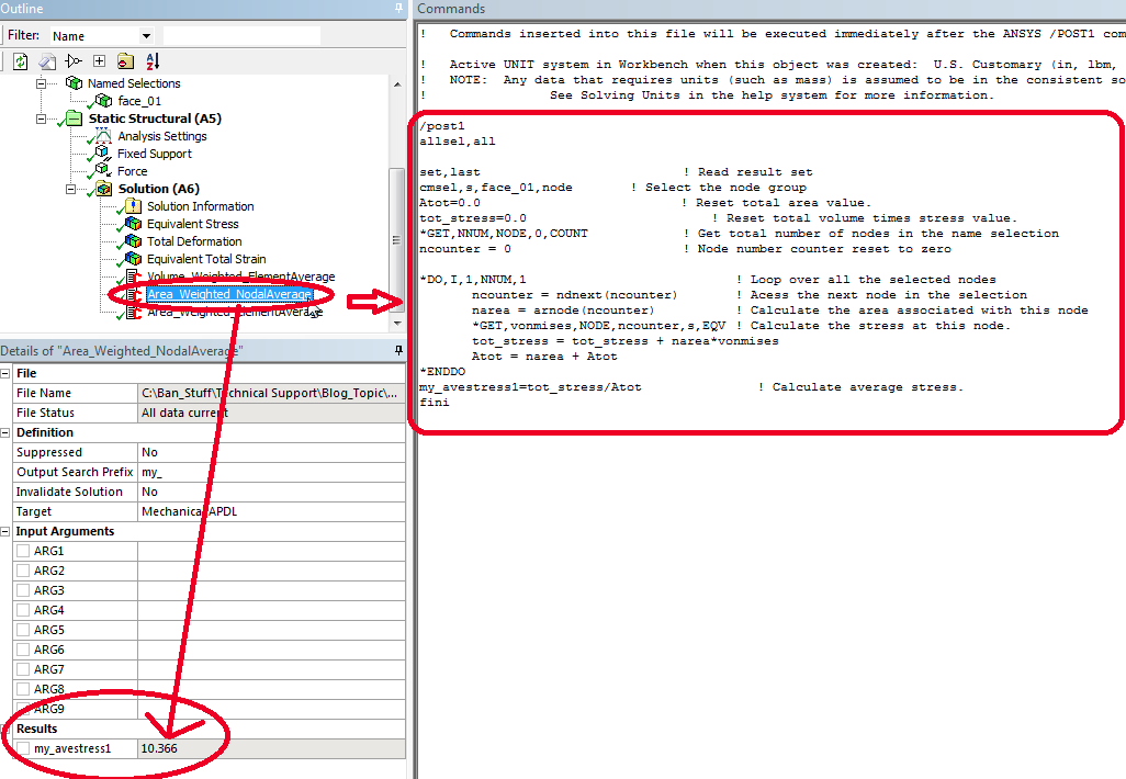
This can be done by implementing the macro in a command object as shown. The weighted area average nodal stress on the surface is reported under the details of the command (in the red circle below) with the parameter named “my_ave_stress1”.

The contents of the command object can be downloaded here.
Note: The surface chosen to do the averaging is defined as named selection ‘Face_01’ (used in the macro). In this technique the weighted averaging is done by calculating area apportioned to the nodes, and multiplied with the corresponding stress values for those nodes, and then summed up, and then we divide that sum by total area of nodes.
Technique 2 : Reporting weighted volume or area average element stress
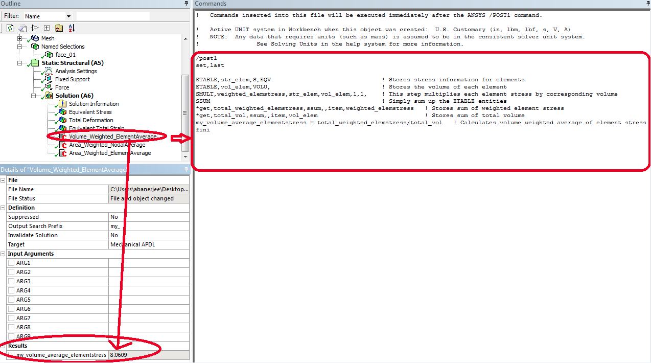
DRD recommends doing element averaging that is weighted based on volume. This can be done with a command object (shown below) and you can download it here.

If the goal is to use the element area to do the averaging, then there is a technique for this as well. This method is written for 3d solid elements belonging to the ANSYS 18x series solid elements such as : 185 (dropped midside node bricks), 186 (20 node bricks), 187 (10 node tets).
In this technique, you define the surface using a named selection (Face_01). You will additionally create a remote point referenced to that named selection. This is a clever trick, since in a solid 3d mesh, it is not directly possible to know the area of the element face easily. By creating a remote point, we are creating contact/target elements which are then tagged to the solid elements overlaid on that surface, and the area of contacts gives us the area of the solid element faces which can then be used for the element averaging.
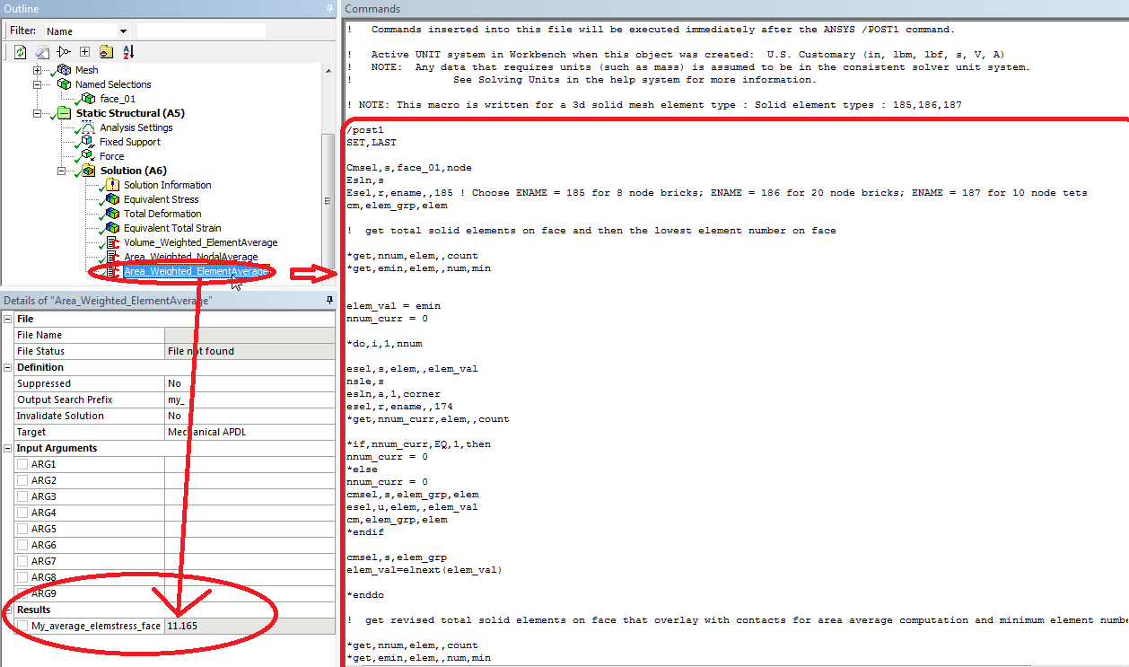
This can be done by implementing the command object as shown. The content of the command object can be downloaded here.

The weighted area average element stress on the surface is reported under the details of the command as shown with the parameter named “My_average_elemstress_face”.
Note: If you are running a SOLID 185, 186 or 187, you need to specify that in the command snippet as highlighted below. In this technique, the weighted averaging is done by calculating area of the elements, multiplied with the corresponding stress values for those elements, summed up, and then we divide that sum by total area of elements.

DRD recommends you test these techniques on a simple part first before attempting on a larger model, and be sure to do the necessary sanity checks to ensure results are accurate.

