Ansys Workbench LS-DYNA

Ansys Workbench LS-DYNA

Ansys Workbench LS-DYNA

Two-day course

The objective of this course is for attendees to develop expertise in the use of Ansys Mechanical for explicit dynamic analysis using Ansys LS-DYNA. Ansys LS-DYNA has a wide variety of applications in many industries such full car crash testing in the automotive industry, windshield bird strike simulation in the aerospace industry, cell phone drop test simulation in consumer electronics, and deep drawing, hydroforming, and superplastic forming simulation in advanced manufacturing.

This 2-day course includes ten workshops and nine instructor-led lectures to cover basic explicit dynamics theory and applications.

Prerequisites for this course are DRD’s Introduction to Ansys Mechanical course and/or proficiency with the Ansys Mechanical user interface. This is a challenging course for proficient users.

Course Requirements:

Ansys Version used to create course content: 2021 R1
Ansys Version DRD instructor will use for the course: 2023 R1
Ansys Version(s) students may use for the course: 2023 R1

Registration for all classes will close 5 business days in advance of the class date. 

Learn more: Agenda + Course Description

Module 1 - Explicit Theory and Workbench LS-DYNA

LS-DYNA 1.gif
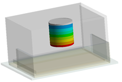
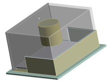
Workshop 1.1 – Taylor Impact

The goal of this workshop is for students to become familiar with the Ansys LS-DYNA workflow and learn how to perform an impact test simulation. In this Taylor impact test, a cylinder made of elastic-plastic steel hits a rigid wall with an initial velocity and the goal is to determine the contact interaction forces and energy exchange from this impact simulation.

Module 2 - Solution Setup, Boundary Conditions, Rigid Bodies

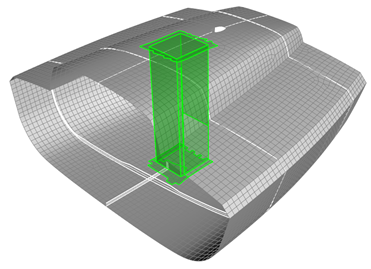
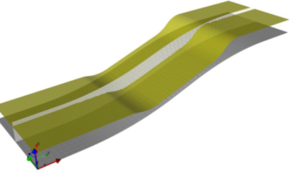
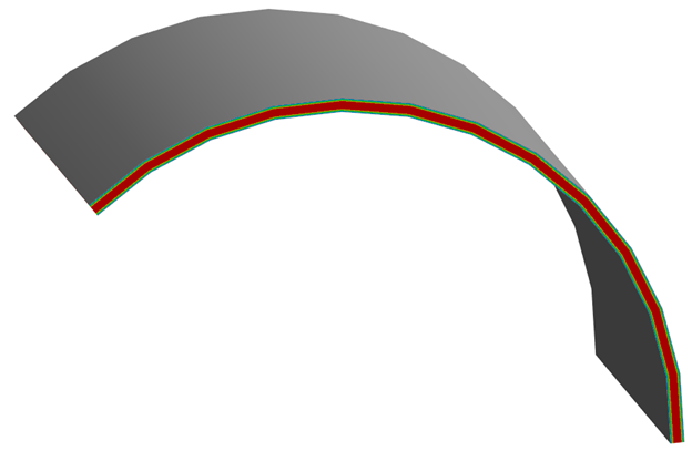
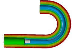
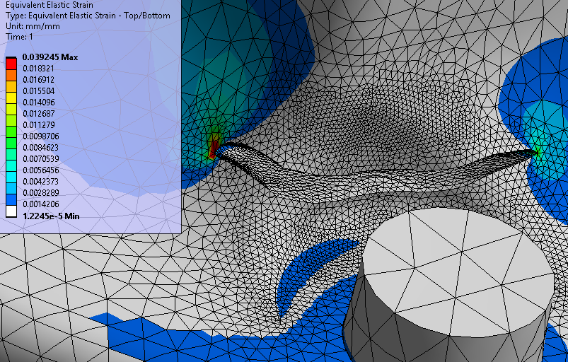
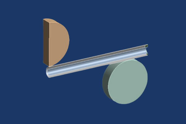
Workshop 2.1 – Rotary Draw Bending
LS-DYNA 3_1a.png

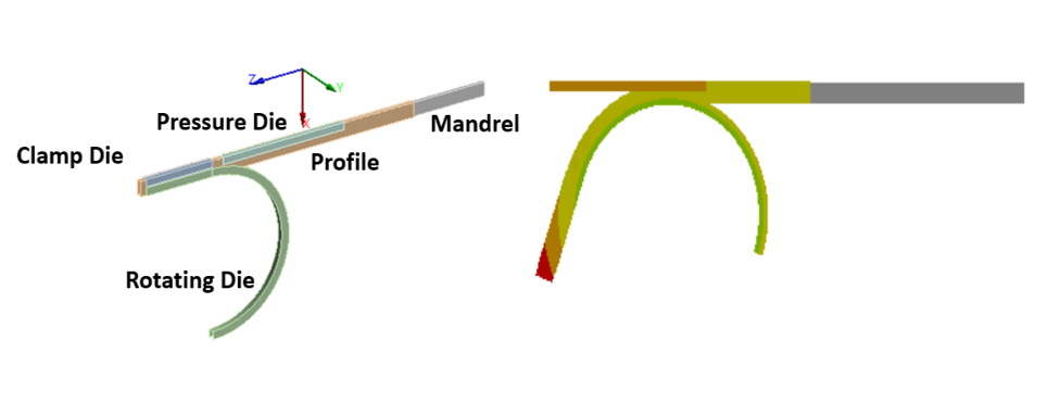
This workshop involves bending a “Profile” by 70 degrees using a rigid tool. In this example, the rigid “Rotating Die” and “Clamp Die” will rotate about the Y axis dragging the “Profile” along as it slides along the stationary Mandrel. The “Pressure Die” translates axially along the Z axis while it maintains pressure against the “Profile” as it’s formed over the circular trajectory of the “Rotating Die”.

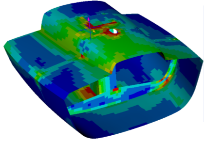
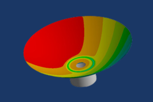
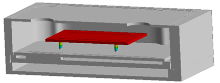
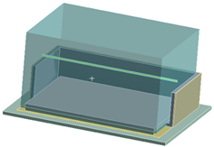
Workshop 2.2 – Drop Test WizardWhatever it is, the way you tell your story online can make all the difference.

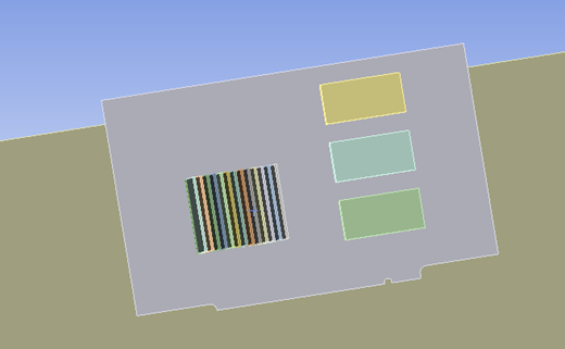
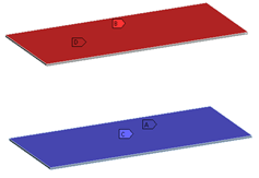
This workshop demonstrates the use of the Drop Test Wizard built into Ansys Mechanical to set up and simulate dropping a circuit board from a height of 1 meter.

Module 3 - LS-DYNA Results and Postprocessing

Workshop 3.1 – Postprocessing with LS-PrePostLS-DYNA 2.2.png

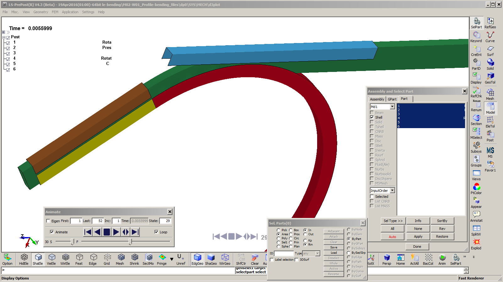
This workshop navigates into the LS-PrePost environment to review some of the postprocessing capabilities with LS-PrePost interface, which is included with Ansys LS-DYNA.

Module 4 - Connections

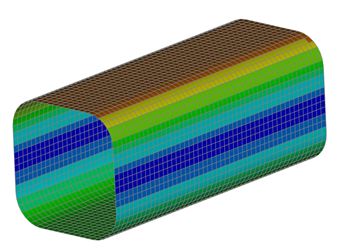
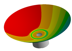
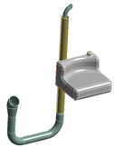
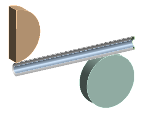
Workshop 4.1 – Impact on Tubes   LS-DYNA 3_1.gif

In this workshop two nested (concentric tubes) are struck by an impactor approaching at an initial velocity of 30 meters per second. The tubes are connected at outer ends through caps and supported by rotatable cylinder.


Module 5 - Quasi-static Analysis and Result Verification

Workshop 5.1 – Quasi-staticLS-DYNA4_1b.pngLS-DYNA4_1a.png

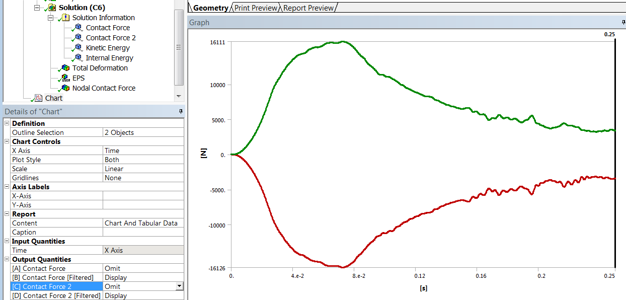
This workshop utilizes the tube impact test example that involves dropping a tool to hit the tubes. In this workshop; however, we conduct a Quasi-static analysis to study the load from a hydraulic cylinder. The speed of the cylinder is based on the hydraulic pump and the controls system and can take a few seconds to run. It would take a long time to run this in the physical time frame, but the concept of Quasi-static simulation can help accelerate it.

Module 6 - Engineering Data and Material Models
Module 7 - Meshing

Workshop 7.1 – MeshingWhatever it is, the way you tell your story online can make all the difference.

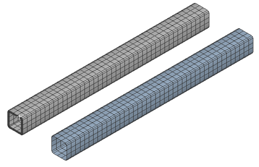
This workshop gives users experience with generating a uniform mesh for both solids and shells with a specific number of element divisions on curved geometry.


Module 8 - Element Formulations

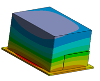
Workshop 8.1 – Drop Test05122021_Drop Test 2.png

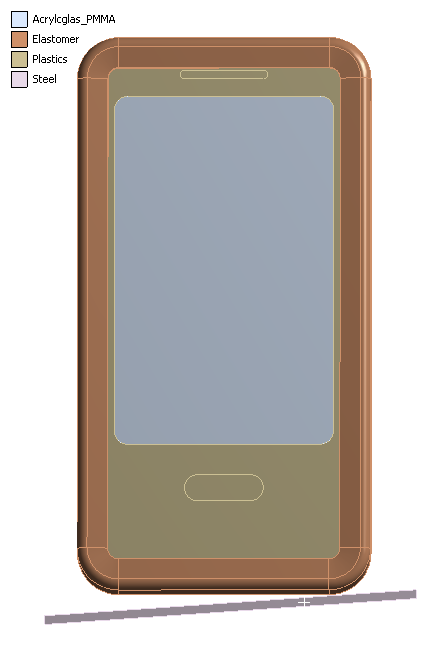
In this workshop we perform a drop test simulation in which we drop a mobile phone from a height of 1.5 meters.


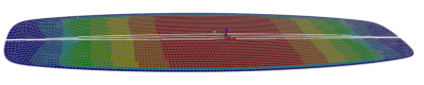
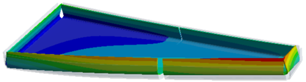
Workshop 8.2 – Bird StrikeLS-DYNA Bird Strike.gif

In this workshop an impact simulation is performed in order to study the effect of a bird strike on an aircraft wing section. The bird is modeled using Smooth Particle Hydrodynamics (SPH).

Module 9 - LS-DYNA Keywords

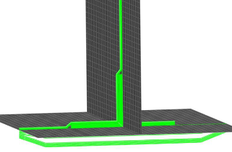
Workshop 9.1 – Crimping ProcessLS-DYNA 8_1.gif

In this workshop, a “Crimper” moves a prescribed velocity and deforms the “Crimp” to create a shaped connection between the bundled wires and “Crimp”.


Course Enrollment and Schedule

Ansys Workbench LS-DYNA

Ansys Composite PrepPost

Ansys Composite PrepPost

Ansys Composite PrepPost

one-day course

This course is geared toward engineers who are designing and analyzing layered composites. The training will cover the correct and efficient use of this technology for the purpose of overcoming some of the inherent challenges in composite modeling such as capturing fiber orientation, model inspection, failure analysis, and parameterization. This training will teach attendees how to make high fidelity layered shell and layered solid models, save time at the post-processing stage, and more.

Prerequisites for this course are DRD’s Introduction to Ansys Mechanical course or equivalent practical experience using Ansys Mechanical. This is a challenging course for proficient users. Please do not register for this course if you do not have the prerequisites. Please contact DRD if you have questions or would like to discuss this with us at support@drd.com.

Course Requirements: 

Ansys Version used to create course content: 2020 R1
Ansys Version DRD instructor will use for the course: 2022 R1
Ansys Version(s) students may use for the course: 2021 R1, 2021 R2, 2022 R1

Registration for all classes will close 5 business days in advance of the class date. 

Learn more: Agenda + Course Description

Workshop 1 - Basic Sandwich Panel

05072021_ACP1.png
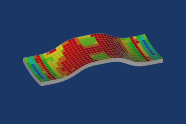
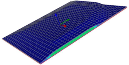
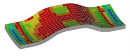
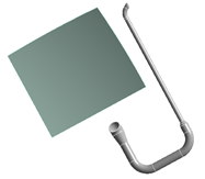
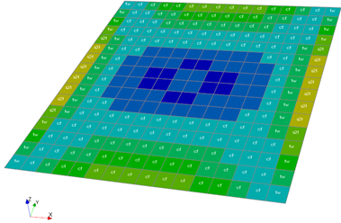
In this workshop the user will learn how to define new composite materials for analysis and start ACP from within Workbench. The user will then learn how to define fabrics, rosettes, oriented selection sets, and modeling plies to create a simple composite sandwich panel.

Workshop 2 - T-Joint

05072021_ACP2.png

This workshop gives the user some experience with using multiple rosettes, multiple oriented selection sets, and tapering of core materials to define complex composite layups.

Workshop 3 - Class 40 - Selection Rules

05072021_ACP3.png

In this workshop users will learn how to use selection rules to modify the composite layup of a class 40 boat in order to increase its reserve against failure.

Workshop 4 - Advanced Sandwich Panel

05072021_ACP4.png

This workshop continues Workshop 1 – Basic Sandwich Panel. The layup is modified and reinforced in order to increase the panel’s strength, and the mesh is refined in order to obtain more accurate results. Selection rules and tapers are employed in order to create a desired layup. 

Workshop 5.1 - Solid Modeling

05072021_ACP5_1.png

In this workshop, users will generate and evaluate a composite model of a doubly-curved tensile test specimen. This model will use solid elements instead of shell elements in order to accurately capture stress distributions in thick geometry where plane stress assumptions do not apply.

Workshop 5.2 - Solid Modeling with Cut-Off Rule

05072021_ACP5_2.png

This workshop demonstrates the use of cut-off rules for ply tapering. It also goes through the procedure of applying a resin material to wedge elements that represent the tapered section where a ply starts or ends in a solid composite model.


Workshop 6.1 – Kiteboard

05072021_ACP6_1.png

This workshop will take users through the complete process of modeling, solving, and post-processing a composite model. Solid geometry will be used to generate a variable core thickness in a complex pattern.

Workshop 6.2 – Post-Processing

05072021_ACP6_2.png

The boat model from Workshop 3 will be used to practice with a variety of post-processing tools, including sampling points to obtain through-thickness results.

Workshop 7 – Parameters in ACP

05072021_ACP7.png

This workshop will use Workbench parameters to modify the laminate of a composite part. Multiple designs will be evaluated in order to identify which design has the best performance in terms of several composite failure modes.

Course Enrollment and Schedule

Ansys Composite PrepPost

Ansys Composite Cure Simulation

Ansys Composite Cure Simulation

Ansys Composite Cure Simulation

One-day course

This 1-day course is designed for engineers who are analyzing the curing process of layered composites. The training will cover the correct and efficient use of this technology for the purpose of simulating the composite curing process to determine degree of cure and process-induced distortions and stresses. Attendees will also learn how to compensate for these distortions in the tool surface so that the final composite structure meets the desired specifications.

Prerequisites for this course are DRD’s Introduction to Ansys Mechanical course and DRD’s Ansys Composite PrepPost course or equivalent practical experience using Ansys Mechanical and ACP. This is a challenging course for proficient users. Please do not register for this course if you do not have the prerequisites. Please contact DRD if you have questions or would like to discuss this with us at support@drd.com.

Workshop 1 - C-Shape Profile Full Cure Simulation

In this workshop attendees will learn how to use ACCS to model the curing of a C-shape composite profile made from carbon fiber prepreg. Completing a thermal simulation of the process yields results such as material state, degree of cure, glass transition temperature, and heat of reaction. From there, a structural analysis of the curing process allows for the prediction of process induced distortions and stresses.

Workshop 2 - C-Shape Profile Fast Cure Simulation

This workshop is nearly identical to the previous workshop with the difference being that the fast solution method is used instead of the full method. This method assumes a uniform temperature distribution and applies to relatively thin (less than 5 mm) composite structures.

Workshop 3 - Tool Compensation

In this workshop users will build on what they learned in the previous workshops to not only predict the composite curing process induced distortions but also compensate for them in the tooling geometry to produce a composite structure that meets the original design specifications. Attendees will also learn how to simulate post-cure trimming operations.

Course Enrollment and Schedule

Ansys Composite Cure Simulation

Ansys Mechanical Thermal Simulation

Ansys Mechanical Thermal Simulation

Ansys Mechanical Thermal Simulation

One-day course

This course provides an introduction to thermal modeling capabilities in Ansys Mechanical. Ansys Mechanical handles conduction and radiation heat transfer including calculation of view factors for surface-to-surface radiation. Mechanical also handles convection heat transfer, primarily as a boundary condition based on a heat transfer coefficient and a bulk temperature. Material properties and heat transfer coefficients can be temperature-dependent.

This course is entirely workshop-based with no dedicated lecture component and takes place over a single day. The emphasis is placed on the creation and solution of practical thermal analyses rather than detailed presentation of heat transfer theory. The goal is to introduce the most important tools for heat transfer analysis and to show best practices for modeling common heat transfer problem types.

This is an advanced course, and attendees are expected to be comfortable with the basics of Ansys Workbench and Mechanical. It is recommended that attendees complete DRD’s Introduction to Ansys Mechanical course prior to attending this course. Engineers already proficient with Ansys Mechanical also have the course prerequisite.

Course Requirements: 

Ansys Version used to create course content: 2023 R1
Ansys Version DRD instructor will use for the course: 2023 R1
Ansys Version(s) students may use for the course: 2023 R1

Registration for all classes will close 5 business days in advance of the class date. 

Learn more: Agenda + Course Description

Workshop 1 – Hazardous Material Cabinet Subjected to Steady Temperature Load

06172021-mechanical Thermal_1.png

In this workshop we model steady-state heat transfer in a hazardous material enclosure. This simplified analysis incorporates convection with the environment as well as internal conduction in a multi-part assembly. We introduce techniques for estimating and assigning convection coefficients based on the temperature difference between the fluid and the convection surface. Temperature-dependent material properties are created and assigned.

Workshop 2 – Parallel Plates with Radiation Heat Transfer

06172021-mechanical Thermal_2.png

In this workshop we introduce radiation heat transfer. We compare the results from using radiation boundary conditions in FEA with hand calculations for a case of two parallel plates of known temperature.

Workshop 3 – Hazardous Material Cabinet Thermal Analysis with Radiation

06172021-mechanical Thermal_3.png

In this workshop we continue Workshop 1 by adding radiation to the model, which allows heat to be transferred to and from an internal cylinder containing hazardous materials.

Workshop 4 – Hazardous Material Cabinet Subjected to Fire

06172021-mechanical Thermal_4.png

In this workshop we continue the analysis on the hazardous material cabinet, this time performing a transient thermal analysis in order to observe the temperatures of the materials after the exterior is exposed to fire.

Workshop 5 – Antenna Subjected to Solar Loads and Thermal Stress

06172021-mechanical Thermal_5.png

In this workshop we model solar radiation using an MAPDL Commands object. We also defeature components that are not important to a thermal analysis, then map the results from the defeatured thermal model onto a full-featured structural model in order to perform a thermal stress analysis.

Workshop 6 – Heat Transfer Analysis of an Electronics Enclosure

06172021-mechanical Thermal_6.png

In this workshop we demonstrate two uses of contact resistance: accounting for imperfect contact and modeling thin bodies with a specified resistance in the thickness direction.

Workshop 7 – Effect of Exhaust Radiation Shield on Windshield

06172021-mechanical Thermal_7.png

In this workshop we examine how a radiation shield surrounding a high-temperature exhaust pipe affects a nearby windshield.

Workshop 8 – Thermal Analysis of Fuel Injection Nozzle with Fluid Flow

06172021-mechanical Thermal_8.png

In this workshop we use Thermal Fluid elements to model fluid flow through a nozzle. The thermal analysis accounts for convection heat transfer between the fluid and the nozzle, as well as a specified mass flow rate of the fluid.

Workshop 9 – Heat Transfer in a Cabinet with Internal Convection

06172021-mechanical Thermal_9.png

This workshop is designed to provide students with practice modeling assemblies. We read the assembly into Mechanical and perform static stress analysis using default bonded contact to hold the parts together. We then use model branching to make a new version of the model, which has no separation contact instead of bonded contact for some of the connections, and we compare the behavior of the models with bonded and no separation contact in the connections.

Workshop A – Radiation Heat Transfer from Exhaust Pipe to Gas Tank

06172021-mechanical Thermal_A.png

In this appendix workshop, we give students the opportunity to practice setting up a heat transfer model without detailed instructions. The goal is to evaluate whether radiation from the exhaust pipe will bring the fuel tank to an unsafe temperature.

Course Enrollment and Schedule

Ansys Mechanical Thermal Simulation

Ansys Mechanical Fracture Mechanics

Ansys Mechanical Fracture Mechanics

Ansys Mechanical Fracture Mechanics

one-day course

Fracture mechanics allows engineers to analyze the integrity of a structural component, where traditional methods of stress analysis are not applicable. Cracks are sharp corners, and traditional finite element analysis does not provide accurate stress at a sharp corner, also known as a singularity. The primary questions engineers are trying to answer when performing a fracture analysis are:

  • Will a crack grow under these loading conditions?

  • Where will the crack grow?

  • How long will it take for a crack to grow until the part breaks?

This 1-day course will give attendees experience in setting up, solving and post-processing finite element models with cracks in structural components. Information, such as Stress Intensity Factors, SMART (Separating, Morphing and Adaptive Remeshing Technology) crack growth and techniques for creating cracks in the finite element model will be covered.

Prerequisites for this course are DRD’s Introduction to SpaceClaim for Mechanical and Introduction to Ansys Mechanical courses. DRD recommends that students who do not have these prerequisites delay attending the course until they attain them. This is a challenging course for proficient users.

Chapter 1 – An Overview of Fracture Mechanics in Ansys

Workshop 1: Ansys Stress Intensity Factor Solution with a Simple Edge Crack ModelFracture_ws1_graphic.png

The objective of this workshop is to provide a simple basis for modeling cracks in Ansys Mechanical. The students start with a 2D plate structure and create an edge crack with the Pre-Meshed Crack capability. The student will then post-process fracture parameters, such as Stress Intensity Factor (SIF), and compare the output with a closed form solution found in many elementary fracture mechanics’ text.

The student is also introduced to residual strength curves, from both the fracture failure mode and the limit load failure mode. These curves help determine the first mode of failure for the structure.

Workshop 2: Calculation of Stress Intensity Factor at an Elliptical CrackFracture_ws2_graphic.png

This workshop expands on the basic setup and output of the previous workshop, into a 3D model. Here, a welded pipe joint is subjected to pressure with a crack on the exterior of the pipe wall. The student will learn how to create an elliptical (or penny)-shaped crack without any prior geometry modification.

3D contours of Stress Intensity Factor are calculated for the initial case of crack size. Then, the student will modify the crack size definition, rerun the model, and compare the two solutions.

Workshop 3: Edge Cracked Plate VCCT Fracture Mechanics with Closed Form SolutionFracture_ws3_graphic (002).png

Like workshop 1, the objective of this workshop is to setup and solve a simple 3D edge cracked plate model under modeI loading. In this instance, the student will use the Virtual Crack Closure Technique. Also known as MCCI (Modified Crack Closure Integral), this method calculates a Strain Energy Release Rate (SERR) for the fracture parameter.

Students will then compare this with a closed form solution, as well as experiment with calculating a Stress Intensity Factor using Irwin’s equation.

Workshop 4: Calculation of Stress Intensity Factor and Energy Release Rate for a Double Cantilever Beam

Workshop 5: ANSYS VCCT Solution of a 4-Point Bend TestFracture_ws4-5_graphic (002).png

Workshops 4 and 5 demonstrate other cases of setting up and solving simple stationary crack models in Ansys Mechanical. Workshop 4 has the student setup a double cantilever beam structure. Workshop 5 uses a 4-point bend structure. Both cases have simple closed form solutions to compare to that allow validation of Ansys fracture results with known solutions.

Chapter 2 – Model Crack Growth in Ansys

Workshop 6: Computing Crack Growth with ANSYS SIFs and the Paris Law on a 2D Pressure VesselFracture_ws6_graphic (002).png

The objective of this workshop is to provide the groundwork for crack growth analysis. In this workshop, students solve a 2D pressure vessel study for varying crack lengths using Ansys Mechanical with a parametric model.

The workshop then provides a basis for computing crack growth information using a spreadsheet, allows the student to experiment with the crack growth computation, and asks several engineering questions:

·         What crack length causes immediate fracture?
·         Is limit load exceeded?
·         Is the curve fit for crack growth adequate for small cracks?


Workshop 7: SMART Crack Growth on Intersecting Pipes04292021_Fracture Mechanics.gif

This workshop is the first of two workshops that demonstrate the use of SMART. Students will learn how to setup an automated crack growth analysis using the Semi-Elliptical Crack combined with SMART Crack Growth object. Detailed definition of the Paris Law material constants for crack growth is also covered.

Automated crack growth has a host of new results post-processing options for Crack Extension, Equivalent Stress Intensity Range and Cycles; students will work through these options as well.


Workshop 8: SMART Crack Growth on a Casting with a Thermal GradientFracture Mechanics Training.png

In this workshop, students learn how to create a crack using a 3D surface representation of the crack surface. This is made possible via the Arbitrary Crack feature, which allows a complex, non-planar 3D surface to be used as a basis for generating a crack mesh.


Workshop 9: SMART Crack Growth on a Casting with an Initial Stress State

This workshop is a continuation of workshop 8, where students load a casting with a thermal gradient and grow a crack. In this workshop, an initial stress state is set up that includes this thermal gradient and bolt pretension. The initial stress state is passed to a downstream analysis where the cyclic load to grow the crack is pressure. SMART crack growth is used here; Ansys automatically handles this initial stress state each time the crack calculation is performed.

Chapter 3 – Modeling Adhesive Failure

Workshop 10: Adhesive Failure Modeling with Contact Debonding

This workshop demonstrates modeling failure of an adhesive layer via bonded contact. Students define a cohesive zone material model with properties for maximum normal stress and critical fracture energy. The benefit of this capability is that the adhesive layer does not need to be directly modeled. This is a huge benefit as the adhesive layer is typically much smaller in thickness compared to the parent parts bonded together. A secondary benefit is the mesh does not need to be the same on either side of the interface, as contact is used to initial tie the parent parts together.


Workshop 11: Adhesive Failure Modeling with Interface Delamination

This workshop demonstrates a second method to simulate interface failure; interface delamination. A similar material model is defined for this method. However, contact is not required for this capability. Instead, the mesh on both parent parts must be the same at the interface with the adhesive. This is accomplished through clever meshing or match mesh controls. The interface delamination capability also has another special use case: delamination modeling with composite models created in Ansys Composite PrepPost.

Course Enrollment and Schedule

Ansys Mechanical Fracture Mechanics