Introduction to Ansys SIwave
Introduction to Ansys SIwave
one-day courseThis course provides an introduction to the Ansys SIwave environment of the Ansys Electronics Desktop (AEDT) Suite. The general problem addressed is that of the PCB type. The course focuses on the use of the SIwave user interface and briefly touches on the HFSS 3D Layout interface. Both of these tools are included in the Ansys SIwave Premium and Ansys Electronics Enterprise licenses. Within these interfaces, one can import ECAD geometry, assign material properties, apply excitations, perform solutions, review analysis results, and generate several types of automatic html reports. We discuss solutions to general electromagnetic problems encountered by most PCB designers. Approaches for calculating trace characteristic impedance, crosstalk, DCIR drop/ohmic loss, S-parameters, signal/power integrity, and capacitor decoupling are addressed.
Most workshops begin with projects where ECAD geometry has already been prepared. DRD encourages students to bring ODB++ or ANSYS EDB files with them to the training (preferably from their workplace) if they desire to test their own geometry.
Additional Course Details
Ansys Version used to create course content: 2019 R1
Ansys Version DRD instructor will use for the course: 2021 R2
Ansys Version(s) students may use for the course: 2021 R1, 2021R2
Registration for all classes will close 5 business days in advance of the class date.
Learn more: Agenda + Course Description
Module 1 - Overview of SIwave and SIwave Basics
Workshop 1.1 — Layout Design Import 
This workshop introduces the SIwave import process and utilities applicable to starting many or most SIwave projects.
Workshop 1.2 — PCB Z0 and Crosstalk Scan
This workshop shows how to automatically and quickly scan the entire PCB or package layout and identify violations with regards to delay, impedance profiles, and crosstalk susceptibility.


Module 2 - Signal Integrity
Workshop 2.1 — Channel S-Parameter Extraction 
This workshop shows the process of setting up ports and extracting the S-parameters for a high-speed channel using ANSYS SIwave.
Workshop 2.2 — TDR Wizard 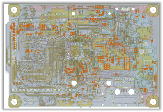
This workshop shows the process of setting up a TDR simulation in ANSYS SIwave to plot the transient impedance variation of single-ended and differential nets. The ANSYS Electronics Desktop Circuit capability is used for the transient simulation.
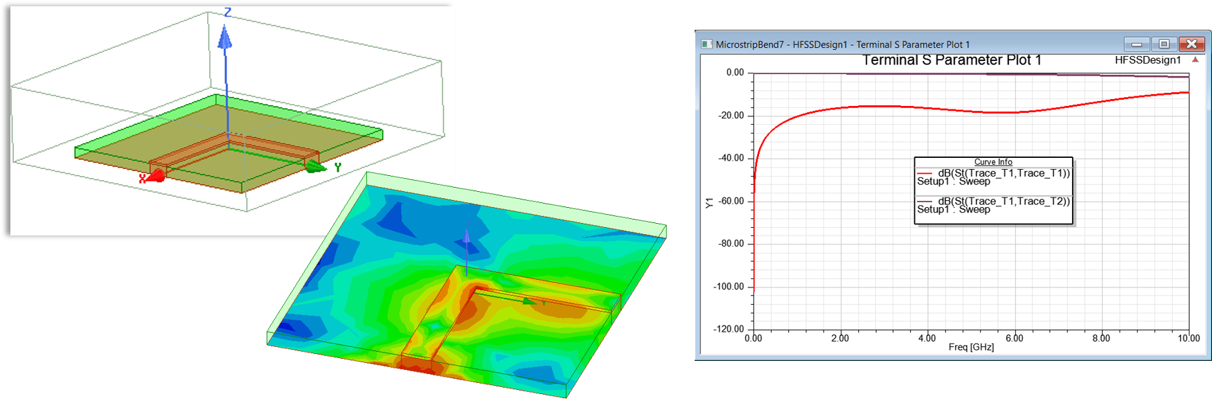
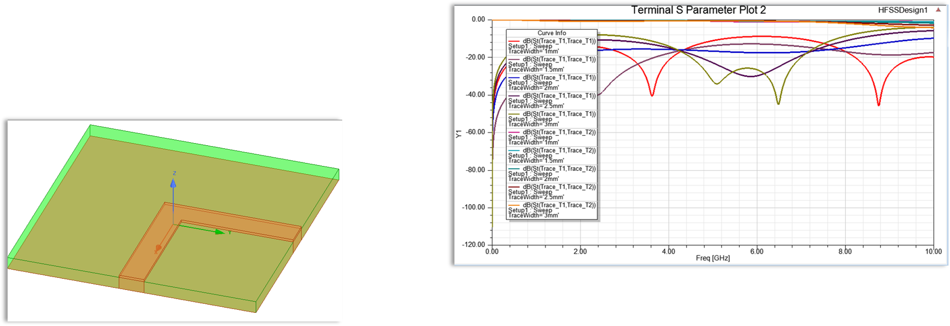
Workshop 2.3: Parametric Analysis
This workshop shows the process of setting up ports, clipping the design and studying the insertion loss variation by sweeping parameters.

Module 3 - Power Integrity
Workshop 3.1: Package PDN RLCG Extraction 
This workshop shows the process of setting up ports and extracting PDN (power distribution network) parasitics for a package design in ANSYS SIwave.
Workshop 3.2a: DC IR Drop Analysis 
This workshop shows the process of setting up a DCIR simulation for a PCB design and validating the electrical performance by identifying regions of current crowding and high current vias for a single-phase VRM system. This workshop also shows how to obtain tabular data for the current and resistance for the vias, and obtain loop resistance and inductance values from the VRM to the IC.
Workshop 3.2b: SIwave DCIR Multi-phase VRM 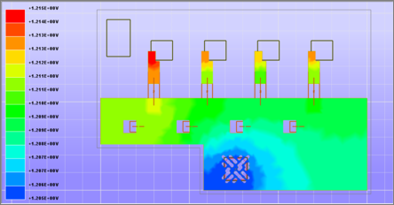
This workshop shows the process of setting up a DCIR simulation for a PCB design and validating the electrical performance by identifying regions of current crowding and high current vias for a multi-phase VRM system. This workshop also shows how to obtain tabular data for the current and resistance for the vias, and how to obtain loop resistance and inductance values from the VRM to the IC.
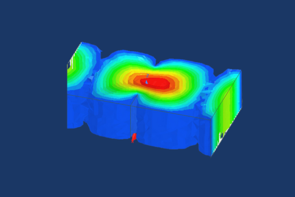
Workshop 3.3: Decoupling Optimization
This workshop shows the process of setting up an ANSYS SIwave PI Advisor simulation, for a PCB design, to validate and optimize the decoupling strategy using ANSYS SIwave.


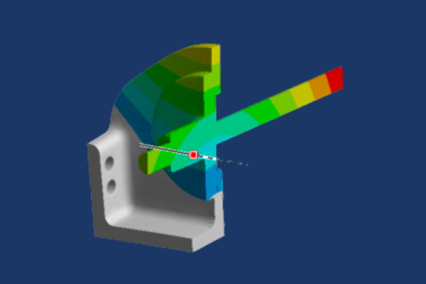
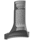
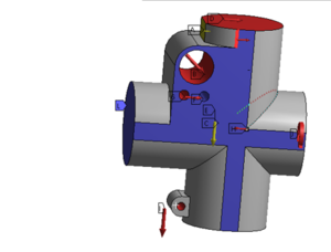
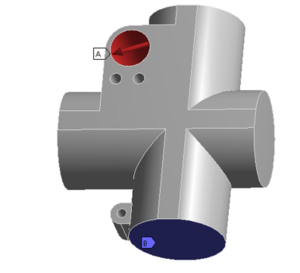
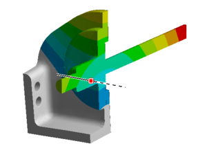
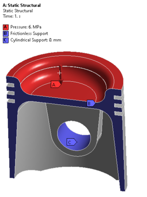
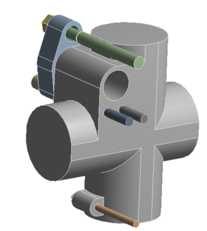
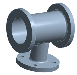 Workshop 1 – Static Stress Analysis of a Fluid Connector
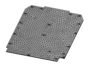
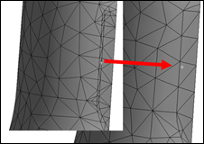

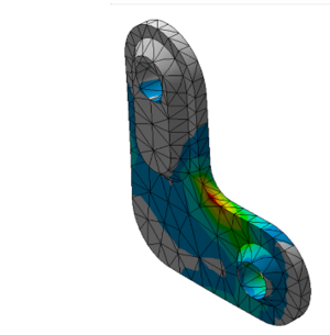

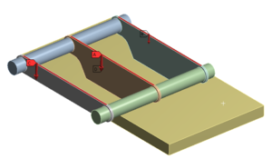

 Workshop B: Ansys Mechanical Integration with Ansys MAPDL (or Ansys Classic)