Released on July 23, 2024, Ansys Mechanical 2024 R2 introduces a powerful new native feature: Fluid Penetration Pressure. While this isn’t entirely new to Ansys, as it has long been part of Ansys APDL, it’s the first time this functionality is available natively in Ansys Mechanical. This feature provides engineers with an efficient way to simulate fluid interactions with structures without explicitly modeling the fluid in finite element analysis (FEA).
What is Fluid Penetration Pressure?
Fluid pressure penetration is a method to capture impinging fluid on a structure, without explicitly modeling the fluid in the finite element analysis.
The fluid penetration pressure method employs information of contact status between contacting bodies to determine where the fluid pressure is applied. The benefit is that this is determined as the contact status evolves over the simulation time, so the region where pressure is applied changes as contact between bodies changes under loading.
Users provide a contact region for the searching algorithm, a starting location for fluid impingement, and the fluid pressure; the solver does the rest. Figure 1 provides a simple view of the starting point on the exterior surface of the structure and the ‘flow’ of the fluid outward.
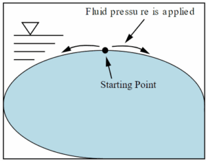
Figure 1: Schematic of Fluid Penetration Pressure Behavior
What is the Application of Fluid Penetration Pressure?
As you perhaps have guessed, the application of fluid penetration pressure is in seals and gaskets for valves, hydraulic cylinders, coil-overs, etc. This allows determination of sealing surface leakage as the structure is loaded and deforms, both from the fluid pressure itself and additional loads in service.

Figure 2: Examples of Gaskets
If engineers can determine seal capability before selling the product, expensive redesign can be circumvented. Seals do not need redesign, re-machining of the sealing surfaces is lessened, and a potentially hazardous leak can be avoided.
Example Simulation with Fluid Penetration Pressure
Here we have a simple representation of a tube, sleeve and O-ring seal in a vehicle strut or coil-over. During the assembly process, the tube is pushed downward to interface with the O-ring. In service, fluid is pushing against the seal from the top in the shown orientation, annotated by the blue arrows in Figure 3. The sleeve is fixed in place.
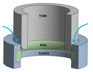
Figure 3: Layout of Simulation with Fluid Impingement Load Direction
As stated previously, analysts need to supply a contact, a starting point, and a fluid pressure magnitude. In the 2D axisymmetric representation of the structure in Figure 3, frictional contact is defined between the three bodies. The Fluid Penetration Pressure object is defined as shown in Figure 4.
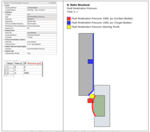
Figure 4: Example Use of Fluid Penetration Pressure Feature, Details, Load, and Graphics
As you can see, we’ve applied the fluid pressure in the second load step; the first load step is moving the tube downward.
I’ll leave you with these final output animations, and a recommendation to visit our website to get access to on-demand training.
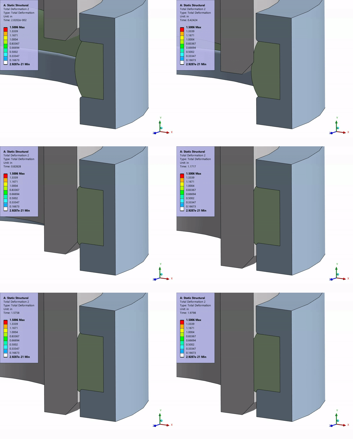
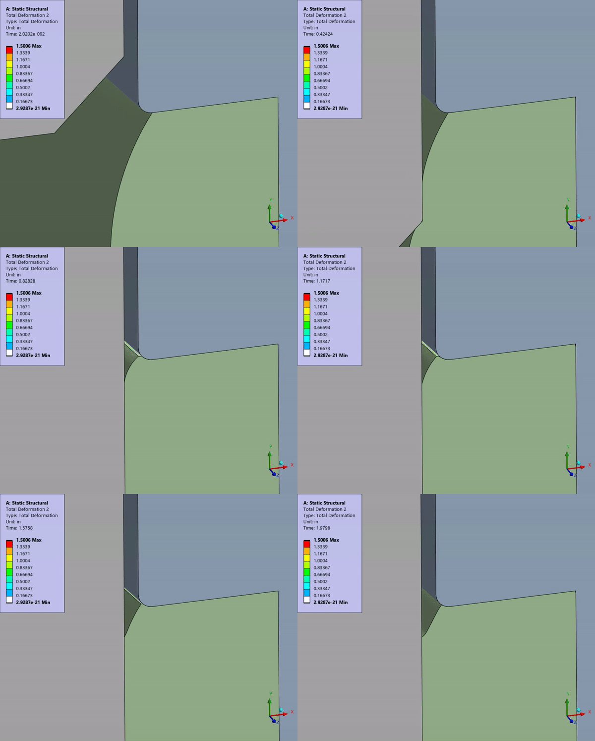
We walkthrough this simulation example as part of our Ansys Mechanical Nonlinear Structural Simulation course. Follow the link here: Ansys Mechanical Nonlinear Structural Simulation – DRD Technology.

