Electronic devices are built on a printed circuit board (PCB), which serves as the foundation that provides the power supply and allows communication between the different devices. Reliability of the PCB is critical to ensure that these electronic devices remain connected, avoiding malfunctions and ensuring the device performs its intended functions for extended periods of time. There are a variety of failure modes that can affect the reliability of a PCB that are discussed in a webinar that DRD Technology conducted, but the subject of this paper is specific to failure due to thermal cycling.
During operation a PCB can undergo a process known as thermal cycling, which is referred to as the repeated exposure of a PCB to fluctuations in temperature during its operational lifecycle. The fluctuations in temperature can be caused by normal operation of the PCB or changes in the environment it is exposed to. These variations in temperature over time can have a profound impact on the solder joints and significantly reduce the life span of the PCB.
As a PCB heats up and cools down through a process known as thermal cycling, there is a phenomenon known as thermal expansion mismatch due to the different materials that make up the board and its components. This cyclic loading causes mechanical strain that may eventually cause the solder joints to gradually deteriorate by causing fractures, cracks, and ultimately failure. These failures or malfunctions may result in erratic electrical connections, degenerate signal quality, or total device malfunctions, all of which can have serious repercussions by reducing the lifespan of the product.
There is a tool within the Ansys portfolio of products called Sherlock that provides fast and accurate life predictions for a PCB early in the design process. Sherlock enables engineers to break free from the design-build-break-repeat cycle that is common in the industry by empowering designers to quickly evaluate the probability of failure due to mechanical, and yes, thermal stress. Sherlock can also be used as a preprocessor for thermal analysis by identifying board level components and assigning material properties appropriately, which can save the designer a significant amount of time.
ECAD Preprocessing in Sherlock
Ansys Sherlock can read all major ECAD formats and can be used as a preprocessor for FEA and CFD analysis to save a significant amount of time. There is an extensive library of parts (over 600,000) and materials within Sherlock that can be used to automatically create geometry and assign material properties, which can reduce preprocessing times an order of magnitude – days to minutes. Sherlock will track over all the details in the ECAD and automatically extract part information from the CAD files, parts list, BOM, etc. See below parts list in Sherlock after reading in ECAD:

Sherlock references a collection of internal databases when assigning material and properties to board components. This streamlined feature can save the analyst a significant amount of time, but it is important to review the part properties and correct them as needed to ensure accurate results. Once the material and properties have been checked for accuracy, the project can be exported into the Ansys Electronics Desktop (AEDT) environment for thermal analysis.
Thermal Analysis in Icepak
It is important to provide Sherlock with accurate board and component level temperatures when predicting the board service life. Without simulation, the analyst would need to rely on experimental data which can be time consuming to produce because it requires a PCB to be manufactured and an experimental procedure developed to mimic conditions in the field. Incorporating thermal analysis early in the design process can provide accurate temperatures for life predictions without which can accelerate product development and reduce costly mistakes that require redesign.
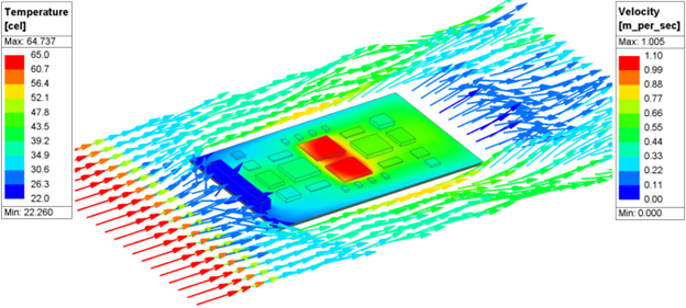
An analyst can read in the exported project from Sherlock and all the materials and associated properties will automatically be assigned. A board can have a great number of components, so using Sherlock as a preprocessor can save the analyst a significant amount of time. See below temperature and velocity field from a thermal analysis solved in Icepak for a board experiencing forced convection cooling:

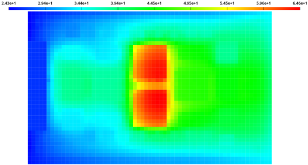
The temperature values on the board from the thermal analysis can be exported into a temperature map file that can be read into Sherlock for accurate thermal cycling. Accurate temperatures are important when predicting the probability of failure due to thermal cycling in solder fatigue analysis.
PCB Life Prediction in Sherlock
Bringing in accurate temperature values and distribution into Sherlock is critical when making life predictions. Sherlock can import images from heat maps found experimentally or temperature map files from thermal simulations. The benefit of using a temperature map file from thermal analysis is that the board does not even need to be manufactured. The analyst simply needs to read the results from Icepak into Sherlock to map the temperatures onto the board for accurate thermal cycling analysis. See below an image of the results from the thermal analysis in the previous section getting mapped onto the board in Sherlock:

If the thermal cycle of the board is such that it simply powers on and off, then only a single temperature map from Icepak may be required if you can assume the off-power state reaches ambient conditions – the analyst only needs a temperature map file that represents the on-power state. There are various scenarios that would require multiple temperature map files to be read into Sherlock for thermal cycling analysis. For example, if the board has high and low-power states, the analyst will want to create a temperature map file for each state of the board to read into Sherlock for thermal cycling. The user can easily specify a maximum and minimum temperature state for the thermal cycle to account for the low and high-power state of the board, as well as ramp and dwell times.
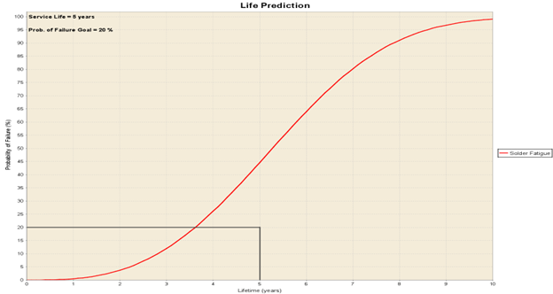
Once the maximum and minimum temperature of the thermal cycle has been defined, a sold fatigue study can be conducted to predict the life of the board. See below:

Reviewing the life prediction graph above indicates that there is a 45 percent change of failure due to thermal cycling. Catching issues like this early in the design process is critical in bringing products to market on time and budget.
Conclusion
Thermal cycling poses a significant risk to the reliability of solder joints in PCB design. The use of virtual prototyping early in the design process allows for a good understanding of the temperature load the PCB will be subjected to in the field, which leads to accurate solder fatigue analysis before the need to manufacture the board and gather experimental data. Integrating simulation into the design process enables engineers to ensure the long-term performance and reliability of electrical devices by identifying thermal issues early. Identifying and resolving the effect of temperature cycling on solder fatigue is essential to producing products that meet or surpass today’s needs in a world where electronics reliability is non-negotiable.

