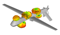
High Performance Computing and Ansys HFSS Design/Simulation

Ansys HFSS simulation tools empower RF engineers to design complete systems in a virtual environment, streamlining the entire development process. With the ability to tackle electrically large EM problems, engineers can efficiently design antennas, include platforms, and even simulate larger environments—all without extensive physical prototyping. This not only saves time but also accelerates the overall development timeline.

How Does Ansys HFSS Handle Electrically Large Problems?

Ansys HFSS offers a variety of solver types, enabling engineers to solve electrically large problems within practical timeframes and computing constraints. For smaller domains, HFSS’s Finite Element Method (FEM) provides high-fidelity solutions. However, as the problem space grows, a full-wave Method of Moments (MoM) solver becomes essential for reducing computational load. For even larger problems, HFSS utilizes ray tracing and physical optics methods, ensuring that even the most extensive simulations are feasible.

What is the Power of Hybrid Solutions in Ansys HFSS?

The real strength of Ansys HFSS lies in its hybrid solution capabilities. By combining FEM for smaller components and MoM or ray tracing for larger structures, HFSS offers a comprehensive approach to RF system simulation. This hybrid method ensures accuracy and efficiency, allowing engineers to simulate complex systems with unparalleled precision.

How Does High Performance Computing (HPC) Enhance Ansys HFSS

Ansys HFSS leverages High-Performance Computing (HPC) to push the boundaries of what’s possible in RF simulation. By parallelizing calculations across multiple CPUs and GPUs, HFSS can handle larger, more complex problems. These calculations can be distributed over a network of computers, enabling engineers to solve massive electromagnetic problems with unprecedented speed and accuracy, whether using local assets or cloud-based resources.

Why Choose Ansys HFSS for Large-Scale RF Simulations?

With its advanced solvers and HPC capabilities, Ansys HFSS is the go-to solution for RF engineers dealing with complex, electrically large problems. Whether you’re designing antennas, integrating platforms, or simulating vast environments, HFSS provides the tools you need to achieve your goals efficiently and effectively in a virtual space.

Wonder how else to optimize antenna simulations with Ansys HFSS? Continue reading our previous blog…


What Are the Key Benefits of Using Ansys HFSS for RF System Design?

The flexibility and power of Ansys HFSS lie in its ability to support a wide range of problem sizes and computational challenges. By allowing RF engineers to choose the appropriate solver and utilize HPC methods, HFSS ensures that virtually any RF system can be designed, simulated, and perfected in a virtual environment, regardless of its size or complexity.


Ready to Deepen Your Understanding? Join Our Three-Part Webinar Series!

In this series, we’ll cover:

Webinar 1: How Can You Design and Simulate Antennas Using Ansys HFSS?

Watch now

Webinar 2: How Do You Simulate Multi-Antenna Systems and Large Problem Spaces with Ansys HFSS?

Watch now

Webinar 3: How Can You Optimize Ansys HFSS Performance with High-Performance Computing (HPC)?

Watch now

Multiple Antennae, Large Problem Spaces, and Co-site Interference

With the rapid increase in devices that rely on wireless communication and data transfer, RF engineers face challenges far beyond analyzing the performance of a single antenna. Modern devices often incorporate multiple antennas, each operating within specific frequency bands. This complicates the RF engineer’s role, expanding their task from understanding the behavior of a single antenna to managing the interactions of multiple antennas on the same platform. The coupling effects between these antennas must be considered, particularly when RF engineers are integrating third-party antenna designs rather than creating them from scratch.

What advantages does Ansys HFSS offer for multi-antenna and large problem space design?

Ansys HFSS is a powerful tool that provides several advantages in tackling the challenges associated with multi-antenna systems. It features a robust parametric antenna design toolkit and a comprehensive component library. This allows antenna designers to either start from a unique design or use an approximate model for system integration and placement studies. Moreover, HFSS’s ability to create “Encrypted 3D Components” enables designers to incorporate high-fidelity models from third-party suppliers into platform simulations without revealing proprietary design information, ensuring accurate RF simulations.

How does HFSS handle the complexities of electrically large problem spaces?

One of the standout features of Ansys HFSS is its hybrid solve technology, which combines finite element (FEM), method of moments (MoM), and shooting and bouncing ray (SBR+) solution domains within a single simulation. This technology is particularly effective in solving electrically large problem spaces, such as those involving multiple antennas and platform integration. By leveraging this technology, RF engineers can efficiently simulate complex scenarios where multiple antennas interact with the placement platform, leading to more accurate and efficient design processes.

How do RF engineers mitigate crosstalk and spurious emissions in multi-antenna systems?

In multi-antenna systems, RF engineers must address issues like crosstalk and spurious emissions, which can occur due to the proximity of antennas on the same platform. Solutions may include optimizing antenna placement, applying tuned filters, adjusting radio channels, or modifying antenna architecture. Ansys HFSS allows engineers to calculate coupling coefficients between antennas with the platform in place, accurately accounting for the constructive and destructive field effects caused by the platform’s presence. These calculations are crucial for optimizing the overall system performance.

What role does Ansys EMIT play in optimizing multi-antenna systems?

Ansys EMIT is a powerful antenna system simulation tool that utilizes the coupling coefficients calculated by HFSS to predict the performance of multi-antenna systems. EMIT’s radio model library, along with feedline components such as filters, can be employed to optimize system performance and address Co-site Interference issues. By conducting these optimizations in a virtual environment, RF engineers can refine their designs before moving on to physical prototyping, saving time and reducing costs.

How do HFSS and EMIT contribute to cost-effective RF system design?

The combination of Ansys HFSS and EMIT provides RF engineers with a comprehensive suite of tools for developing and optimizing RF systems in a virtual space. This approach significantly reduces the need for physical prototyping, leading to faster development cycles and lower project costs. By leveraging the advanced capabilities of HFSS for antenna design and placement, along with EMIT’s system-level simulation and optimization tools, engineers can ensure that their RF systems perform optimally before committing to hardware, thus enhancing the overall efficiency and effectiveness of the design process.


Ready to Deepen Your Understanding? Join Our Three-Part Webinar Series!

In this series, we’ll cover:

Webinar 1: How Can You Design and Simulate Antennas Using Ansys HFSS?

Watch now

Webinar 2: How Do You Simulate Multi-Antenna Systems and Large Problem Spaces with Ansys HFSS?

Watch now

Webinar 3: How Can You Optimize Ansys HFSS Performance with High-Performance Computing (HPC)?

Watch now 

How Does Ansys HFSS Optimize Antenna Design and Performance?

Wireless communication permeats all aspects of daily life. From cellular phones to military craft and everything in between, wireless data transfer and communication is being implemented on a great variety of electronic devices. This wireless connectivity necessitates use of an antenna on each device, both large and small. There are many types of antenna designs. The particular antenna architecture chosen is a function of the application, desired frequency band (or bands) of operation, and required range of effectiveness.

What Makes Antenna Design and Wave Propagation So Complex?

The physics of wave propagation from an antenna is inherently a 3D phenomenon, and as such the engineering calculations underpinning or describing these devices can be quite difficult to formulate in an analytical form. Ansys HFSS facilitates solution of the full-wave electromagnetic field problem in any arbitrary 3D geometry by way of a conformal finite element method. Furthermore, adaptive mesh procedure employed by Ansys HFSS results in the most accurate solution for the lowest computational cost required to resolve the propagating field solution.

Ansys HFSS can be used to predict the behavior and performance of virtually any radiating antenna structure. This fact, coupled with the powerful RF-centric antenna parameter focused post-processing features, allows the antenna designer to fully embrace the approach of “virtual prototyping” and optimize antenna performance in the virtual space, prior to physical prototyping.

How Does Platform Placement Affect Antenna Performance?

Stand-alone antenna behavior is not the sole concern of many RF engineers. Even if the RF engineer is not designing an antenna from concept, antenna performance when placed “on platform” can significantly deviate from the published antenna specifications provided by the antenna manufacturer. The antenna loading and field warping resultant from the radiating or receiving devices proximity to larger platform structures must be taken into account when devising the RF system performance. In addition to antenna component design, the effects of platform placement can be predicted with equal accuracy to the antenna design problem using Ansys HFSS. The large bodies associated with the platform can be included in the simulation. For electrically large platforms, Ansys HFSS can also incorporate “hybrid field solution” methods such that less computationally intense approaches such as Method of Moments (MoM) and/or ray tracing/physical optics approaches can also be used on large domains of the computational space.

By utilizing a virtual prototyping approach in the RF platform design workflow, Ansys HFSS allows for compressed design cycles, fewer design iterations, and reduced physical prototyping iterations. Ultimately, this translates to a reduced development cost.

What if you have many antennas near each other? Will they interfere with one another?  Continue reading on our following blog….

Ready to Deepen Your Understanding? Join Our Three-Part Webinar Series!

In this series, we’ll cover:

Webinar 1: How can you effectively design and simulate antennas with Ansys HFSS? Watch now 

Webinar 2: What strategies can be used for simulating multi-antenna systems and large problems?

Date: September 10, 2024, Time: 9:00 AM – 9:45 AM (CDT)

Webinar 3: How can you optimize Ansys HFSS solver technologies? 

Date: September 17, 2024, Time: 9:00 AM – 9:45 AM (CDT)

Register now to secure your spot! By registering, you will receive confirmation for the first webinar immediately and reservation emails for subsequent sessions at a later date. Don’t miss this opportunity to gain valuable insights and optimize your antenna designs.

My Journey from a Customer to a Team Member of 15 Years

The first time I seriously considered a career in engineering, I was a senior in high school. I initially chose physics as my major, but changed to engineering as I thought it would be easier to find a job in any industry with an engineering degree than with a science degree. The change was indeed hard, but I was up for the challenge as engineering seemed to be an invaluable choice for job security.

I began my career in the hard disk industry where I worked on projects looking through nitty gritty numbers and eventually found a desire to work in simulation. I first worked for a company in Oklahoma City in the late 90’s where DRD was the Ansys supplier but was not in a role to directly work with the software itself. This was when I first discovered DRD Technology and Ansys simulation.

I then relocated to Salt Lake City, taking on a role with a medical device company where I used Fluent to perform fluid dynamics work. When I was working in this role, I was also completing my Doctor of Philosophy degree in Mechanical Engineering. I saw a job posting from DRD Technology on the Oklahoma State University school website, and since Oklahoma was home, and I was already a little familiar with the company, it felt like this was a great opportunity.


Reflecting on my Time at DRD Technology

Since I had exposure to DRD Technology at previous companies, I now have a seasoned view as a customer and as a team member of DRD Technology. Over the past 15 years, in roles including Senior Applications Engineer and now Chief Technologist, I have had the opportunity to work on some incredible projects.

First, since Ansys is a company that is constantly innovating, a large part of my job is to keep up with the latest developments and evaluate them for our team. When I see a new tool that could be useful, I evaluate it thoroughly to ensure it meets our needs and can integrate smoothly into our workflow. One focus area for me has been on a tool called HFSS, which has become a cornerstone of our company’s offerings, and my role has continued to evolve as I work to identify new Ansys technologies that enhance our company’s offerings.

In general, my role is 80 percent pre-sales work and 20 percent supporting technical questions and conducting training courses periodically. Pre-sales allows me the opportunity to work closely with the sales team in the early stages to understand the client’s needs and requirements, and then develop a solution that would meet those needs.


Over the years, I have worked on many different projects. One of the most memorable was a pre-sales project for uAvionix four years ago. uAvionix is a company that builds innovative products for aircraft many of which have integrated RF antennas and my project was to simulate one of their products as “proof-of-concept” effort. When I presented the results to the client, the output from HFSS and measured scope trace results on the same graph were practically identical! I was completely amazed at the accuracy of the simulation in this case. Most numerical simulations are good if they fall within 10 percent of measured data, but this HFSS solution was within <1% of the measured data. That was the first time I ever experienced a predictive physics simulation being that “predictive.” This specific project has always been stuck in my mind; it was quite amazing.